N1-HV/AC Series
User Manual
4
5
N1-HV/AC Series
User Manual
2.3 Explanation of symbols
3. Introduction
3.1 Basic features
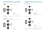
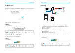
The N1-HV series hybrid inverters apply to PV energy storage system with PV module, battery, loads and grid.
The N1-AC series AC coupled inverters apply to energy storage system with battery, loads and grid.
The energy produced by PV system shall be used to optimize self-consumption, excess power charge battery and the rest power
could be fed into the grid. Battery shall be discharged to support loads when PV power is insufficient to meet self-consumption. If
both PV power and battery power is insufficient, the system will take power from grid to support loads.
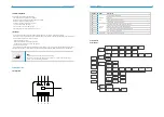
This section gives an explanation of all the symbols shown on the type label.
Symbols on the Type Label
CE mark. The inverter complies with the requirements of the applicable CE
guidelines.
TUV mark.
Danger of high voltages.
Danger to life due to high voltages in the inverter!
Danger.
Risk of electric shock!
The inverter cannot be disposed of together with the household waste.
Disposal information can be found in the enclosed documentation.
Don’t work on this inverter until it is isolated from battery, mains and
on-site PV generation suppliers.
Danger to life due to high voltage.
There is residual voltage in the inverter which needs 5 min to discharge.
Wait 5 min before you open the upper lid or the DC lid.
Beware of hot surface.
The inverter can become hot during operation. Avoid contact during
operation.
Figure 3-1 PV Energy Storage System
Symbol
Explanation
PV Panels
Battery
Normal Load
Grid
Meter
Hybrid Inverter
Monitor
DANGER!
◆
PV strings will produce electrical power when exposed to sunlight and
can cause a lethal voltage and an electric shock.
◆
Only qualified personnel can perform the wiring of the PV panels.
◆
Do not open the enclosure when the inverter is running. Unauthorized
opening will void warranty and warranty claims and in most cases termi-
nate the operating license.
◆
When the enclosure lid is removed, live components can be touched
which can result in death or serious injury due to electric shock.
◆
Operating a damaged inverter can lead to hazardous situations that
can result in death or serious injuries due to electric shock.
◆
Batteries deliver electric power, resulting in burns or a fire hazard
when they are short circuited, or wrongly installed.
◆
Lethal voltages are present at the battery terminals and cables
connecting to the inverter. Severe injuries or death may occur if the
cables and terminals in the inverter are touched.
◆
PV negative (PV-) and battery negative (BAT-) on inverter side is not
grounded as default design. Connecting PV- or BAT- to EARTH are
strictly forbidden.
WARNING!
◆
Do not disconnect PV connectors, AC connector or battery connec-
tors while the inverter is running. De-energize from all multiple power
sources. Wait 5 minutes for the internal capacitors to discharge. Verify
that there is no voltage or current before disconnecting any connec-
tors.
Use personal protective equipment, including rubber gloves and prote-
tive boots during the installation or maintenance.
CAUTION!
Do not touch any hot parts (such as the heat sink) during operation, The
temperature of inverter surface might exceed 60
℃
during working
CAUTION!
◆
Electrical installation and maintenance must be carried out by
competent electricians according to local regulations.
◆
Do not open inverter cover or change any components without RENAC
Power’s authorization, otherwise the warranty commitment for the
inverter will be invalid.
◆
Usage and operation of the inverter must follow instructions in this
user manual, otherwise the protection design might be useless and
warranty for the inverter will be invalid.
NOTE!
◆
Electrical installation and maintenance must be carried out by
competent electricians according to local regulations.
The inverter built-in RCMU will exclude possibility of DC residual current
to 6mA, thus in the system an external RCD (type A) can be used(≥30mA).
NOTICE

