background image

N1-HV/AC Series

User Manual

6

7

N1-HV/AC Series

User Manual

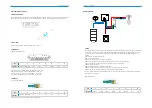
3.2  Work modes

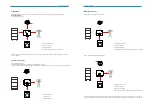
The N1-HV Series hybrid inverter has the following work modes based on your configuration and layout conditions.

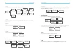
Work mode: Self-use

Priority: load>battery>grid 

Self-consumption of PV renewable energy is the highest priority.  The PV excess is used to charge the batteries, then fed 

back into the grid. 

Priority:load>grid>battery

This mode applies the area that has high feed-in tariff and export control.

The PV generated power will be used to supply the loads firstly, then feed into the grid. The excess power will charge the battery. 

Work mode: Feed in Pirority

1)  Generated solar energy

2)  Load consumption

3)  Storage in battery

4)  Feed the excess solar energy into the grid

1)  Load consumption

2)  Feed into grid

3)  Charge the battery

3

4

1

2

3

2

1

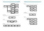
This mode applies the area that has electricity price between peak and valley. User can use off-peak electricity to charge the 

battery. The charging and discharging time can be set flexibly, and it also allows choosing whether charge from the grid or not.

Work mode: Force time use

Priority: battery>load>grid (when charging)

Priority: load>battery>grid (when discharging)

1)  Generated solar energy

2)  Storage in battery

3)  Load consumption

4)  Grid supply power when the battery capacity is not enough

1)Generated solar energy

2)Load consumption

3)Self-use from battery

4)Grid supply power when the battery capacity is not enough

2

4

1

3

3

4

1

2

Summary of Contents for N1-AC Series

Page 1: ...N1 HV 3 0 N1 HV 3 68 N1 HV 5 0 N1 HV 6 0 N1 AC 3 0 N1 AC 3 68 N1 AC 5 0 N1 AC 6 0 UserManual Series N1 HV AC...

Page 2: ...nsportdamage 13 5 3 Installationprecaution 13 5 4 Availablespace 13 5 5 Preparation 13 5 6 Installationsteps 15 5 7 ElectricalWiringConnection 16 5 7 1 PVWiringConnection 17 5 7 2 BatteryConnection 18...

Page 3: ...t 2 2Important safety instructions 1 2 Target group This manual is intended for quali ed electrical technical personnel who are responsible for hybrid inverte AC coupled installation and commissioning...

Page 4: ...ill void warranty and warranty claims and in most cases termi nate the operating license When the enclosure lid is removed live components can be touched which can result in death or serious injury du...

Page 5: ...rority 1 Generated solar energy 2 Load consumption 3 Storage in battery 4 Feed the excess solar energy into the grid 1 Load consumption 2 Feed into grid 3 Charge the battery 3 4 1 2 3 2 1 This mode ap...

Page 6: ...blackout 1 Generated solar energy 2 Storage in Battery 3 Load consumption 4 Grid supply power Figure 3 2 Terminals 2 4 1 3 WARNING Make sure the load powering rating in within the EPS s output rating...

Page 7: ...rated Duration s Max Efficiency Euro Efficiency MPPT Efficiency Max Battery Discharge Efficiency DC Insulation Monitoring Input Reverse Polarity Protection Anti island Protection Residual Current Moni...

Page 8: ...5 Make sure the installation site does not fall into one of the following conditions Do not install the inverter in direct sunlight Do not install the inverter on ammable construction material Do not...

Page 9: ...ake sure the 4 mounting bars on the back of the inverter is xed well with 4 grooves on the bracket Drill holes with 10 driller carefully make sure the holes are deep enough at least 45mm for install a...

Page 10: ...ugs are similar with PV plugs please con rm before use it 1 Turn off the DC switch 2 Prepare 2 5 4mm2 PV cable and PV plugs as below 3 Strip 7mm of the conductor with stripping plier Use a suitable st...

Page 11: ...tery Power Cable Connection 1 Prepare the tin plated cables with a conductor cross section of 4 to 6 mm AWG 10 2 Strip 15mm off the conductor Use a suitable stripping tool for this e g Knipex Solar 12...

Page 12: ...land torque 4 Nm 5 Nm Make sure that the rib of the terminal block and the groove on the housing engage perfectly until a Click is heard or felt 5 7 3AC Output Connection N1 HV AC series inverters hav...

Page 13: ...uirements of local Australian grid code AS NZS 4777 2 which among speci c requirements for connection calls for compatibility with Demand Response Enabling Devices DRED The DRED is under control of a...

Page 14: ...g Comm Addr PV Connection Comm OK PV Connection Multi OK Settings Data Time Work Mode PV Config Normal Power W Battery XX XX XX XX XX Normal Ppv W Pbat W Normal Pac W Pfeed W Pload W Normal ENV_S Char...

Page 15: ...OK Feature Remote Control DRM0 Meter Setting Meter Setting Disable OK Normal Power W Battery XX XX XX XX XX Normal Ppv W Pbat W Normal Pac W Pfeed W Pload W Normal ENV_S Charger_S Inv_S Normal WorkMo...

Page 16: ...Time Use OK Work Mode Backup Use OK Work Mode Feedin Use OK Work Mode FFR Use OK This function can set the mode of PV input There are two modes for selection Comm and Multi The Comm mode means single...

Page 17: ...Press up or down button to set the parameters of battery Press OK to con rm I Off Grid Battery Battery Awaken No OK Battery Dischr Max Curr 25 0A OK Battery Chr Max Curr 25 0A OK Battery Min On Grid S...

Page 18: ...k help from us if not go back to normal state Grid is lost System will reconnect if the utility is back to normal Or seek help from us if not go back to normal state Grid voltage out of range System w...

Page 19: ...seek help from us if not go back to normal state Other device fault Turn off the PV battery and grid reconnect them Or seek for help from us if cannot back to normal The residual current circuit is f...

Page 20: ...Have it carried out according to local waste handling regula tions Please be sure to deliver wasted inverters and packing materials to certain site where can assist relevant department to dispose and...

Reviews: