5
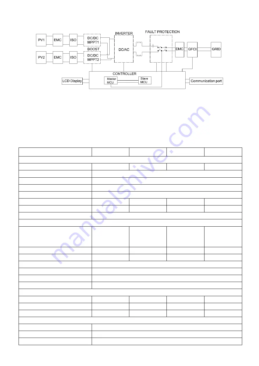
2.2 Electrical system design
Figure 2-3 wiring diagram of the inverter system
Please refer to chapter 3 for the detail connecting and install methods.
2.3 Technical data
Model
NAC10K-LV
NAC12K-LV
NAC15K-LV
NAC20K-LV
DC Input Data
Max. Recommended PV Power
16900W
20800W
22100W
26000W
Max.DC Input Voltage
800V
MPPT voltage Range
200-650V
Start-up Voltage
250V
No. of MPP Trackers
2
No. of Input Strings per Tracker
2/2
2/3
3/3
3/3
Max. DC Input Current
26A/26A
26A/30A
30A/30A
30A/30A
DC Switch
Integrated
AC Output Data
Rated AC Power
11000@208Vac
12000@220Vac
13000@240Vac
14000@208Vac
15000@220Vac
16000@240Vac
15000@208Vac
16000@220Vac
17000@240Vac
17000@208Vac
18000@220Vac
20000@240Vac
Max.output power
13000VA
16000VA
17000VA
20000VA
Max. AC Current
32A
40A
43A
48A
Rated AC Voltage Range
150-300V
Grid frequency/ range
50Hz/60Hz ; ±5Hz
Adjustable Power Factor[cos φ]
0.8leading ~0.8lagging
Output THDi(@Rated Output)
<3%
Efficiency
Max.Efficiency
98.30%
98.40%
98.50%
98.50%
Euro Efficiency
98.00%
98.10%
98.20%
98.20%
MPPT Efficiency
99.90%
99.90%
99.90%
99.90%
Protection
DC Insulation Monitoring
Integrated
Input Reverse Polarity Protection
Integrated
Anti-island Protection
Integrated
Summary of Contents for NAC10K-LV
Page 1: ...0 ...
Page 21: ...20 P N 422 00069 02 ...


