background image


19


Appendix A: FAQ (Frequently asked questions)                         

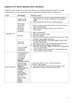
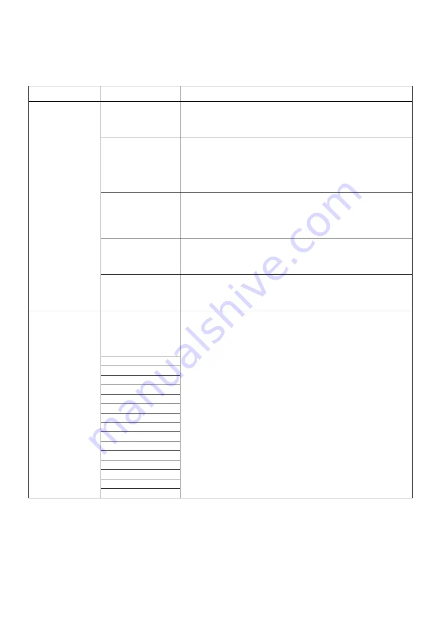
Sometimes, the PV system does not work normally; we recommend the following solutions for average 

troubleshooting. This can help the technician to understand the problem and take a proper action. 

Fault 

LCD display 

Possible actions 

Clearable Fault 

Isolation Fault1 
Isolation Fault2 

1.  Check whether the inverter is earthed and test impedance 

between PV (+) & (-) and the impedance must exceed 
3MΩ; 

2.  Check whether the AC-side has contacts with earth. 

Grid Faults: 
10min OVR 
Fault OVR 
Fault UVR 
Fault OFR 
Fault UFR 

1.  Wait for 5 minutes, if the grid returns to normal, PV inverter 

automatically restarts. 

2.  Make sure grid voltage and frequency meet the local 

specifications. 

No utility 

1.  Grid is not connected. 
2.  Check grid connection cables. 
3.  Check grid usability. 
4.  If grid is ok and the problem exists still, maybe the fuse in the 

inverter is open, please call service. 

 
Low Temp 
Over Temp 

1.  The internal temperature of inverter is higher or lower  than 

specified normal value. 

2.  Find a way to reduce or increase the ambient temperature. 
3.  if the problem remains, please call local service 

PV over Voltage: 
PV1OVFault 
PV2OVFault 

1.  Check the open PV DC voltage, and see if it is greater than 

or too close to 550VDC 

2.  If PV DC voltage is less than 550VDC, and the problem still 

occurs, please call local service. 

Permanent Fault 

Consistent Faults: 
Consist VGrid 
Consist Freq 
Consist GFCI 
Consist DCI 


1.  Disconnect all PV (+) or PV (-) from solar panels 
2.  Wait for a few seconds. 
3.  After the LCD switches off, reconnect and check again. 
4.  If the problem remains, please call local service. 

RelayFail 
EEPROM R/W Fail 
Sci Comm lose 
Spi Comm lose 
BusHFault 
GFCIDeviceFault 
IGridDevice 
PLLFault 
AutoTestFail 
PV Config fault 
Fan error 
DCI out range 
OCPV1 
OCPV2 
OCIGrid 


Summary of Contents for NAC4K-DS

Page 1: ...0...

Page 2: ...n 8 3 2 Installation environment 8 3 3 Installation position 9 3 4 Mounting procedure 10 3 5 Electrical connection 11 3 6 Starting the inverter 14 4 User interface 14 4 1 Led and key 14 4 2 LCD displa...

Page 3: ...ghout the manual important information is shown at different levels depending on the character of the information as shown here Safety information important for human safety Violation of warnings may...

Page 4: ...fore installing the inverter Check the voltages of the solar modules and make sure they are within the limits of the inverter specifications before connecting them to the inverter Installation Only tr...

Page 5: ...ters 2 1 Mechanical design Figure 2 1 shows the outline dimensions of NAC4K DS NAC5K DS NAC6K DS NAC7K DS NAC8K DS Figure 2 1 Outline dimensions Figure 2 2 shows the electrical terminals of NAC4K DS N...

Page 6: ...3 I O Port 4 Communication port 5 AC terminal 6 LCD 7 LEDs Run Fault 8 Key 2 2 Electrical system design Figure 2 3 wiring diagram of the inverter system Please refer to chapter 3 for the detail conne...

Page 7: ...DC Insulation Monitoring Integrated Input Reverse Polarity Protection Integrated Anti island Protection Integrated Residual Current Monitoring Integrated Over heat Protection Integrated AC Overcurrent...

Page 8: ...49 CZ Czech Republic power Grid meet Grid standards EN50438Y2007 CZ 20 IEC61727 India power Grid 21 Korea Korea power Grid 22 EN50549 SW Sweden power Grid 23 China W China power Grid Grid voltage rang...

Page 9: ...DS and 3 PV connectors for NAC7 8K DS There are 2 PV connectors for NAC4 5 6K DS and 3 PV connectors for NAC7 8K DS Figure 3 1 package information 3 2 Installation environment 1 In order to achieve o...

Page 10: ...must be suitable for the inverter s weight and dimensions 2 Mount on a solid surface 3 Select a well ventilated place sheltered from direct sun radiation Figure 3 3 installation position In considerat...

Page 11: ...holes in the wall according to the dimensions Step2 Fix the wall mounting bracket on the wall with 4 expansion bolts in accessory bag Setp4 Place the inverter on the wall mounted bracket and install...

Page 12: ...inverter There are 2 trip thresholds for the RCD as required for certification IEC 62109 2 2011 The default value for electrocution protection is 30mA and for slow rising current is 300mA Connect the...

Page 13: ...s with DC connector otherwise it will cause damage to inverter 3 Make sure the maximum open circuit voltage Voc of each PV string does not exceed the inverter input voltage Vmax under any condition 4...

Page 14: ...d 1000m 2 Communication lines must be separated from other power lines to avoid communications interference Remark RS485 port PIN3 A PIN4 B Figure 3 9 RS485 Port Figure 3 10 RS485 in multiple series F...

Page 15: ...ge 16 chapter 4 3 Step4 Then the inverter will turn into self check mode and the LCD panel will display the remaining time of connect simultaneously Step5 After the inverter turn into normal mode it f...

Page 16: ...er W Clear events Power W Factory setting Power W Clear E total Power W PF xxx Power W Setting Add Pac W Factory setting English Factory setting VDE4105 Factory setting 2 Factory setting Factory setti...

Page 17: ...xport power 5 Set Export power as 1 press pushbutton long to save the value 4 7 Self Test in accordance with CEI 0 21 Applies to Italy only The self test is only required for inverters which are commi...

Page 18: ...ys setting Other AUTOTEST enter into Auto Test interface 4 Click Execute to start the test 5 The inverter will automatically run the test until the screen shows Test end 6 Click Read to read the test...

Page 19: ...Detailed information about the entire system modules circuits etc 5 Documentation of previous claim exchanges if applicable In the case of an exchange the remainder of the warranty entitlement will b...

Page 20: ...bility 4 If grid is ok and the problem exists still maybe the fuse in the inverter is open please call service Low Temp Over Temp 1 The internal temperature of inverter is higher or lower than specifi...

Page 21: ...20 P N 422 00022 02...

Reviews: