5
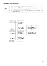
Figure 2-2 Electrical Terminals
Remark:
For CEI standard, DRM S0 is the DI port, corresponding to PIN5 (GND), PIN6 (DI input port) of RJ45.
1
DC (PV terminal)
2
DC Switch
3
I/O Port
4
Communication port
5
AC terminal
6
LCD
7
LEDs
(
Run/Fault
)
8
Key
2.2 Electrical system design
Figure 2-3 wiring diagram of the inverter system
Please refer to chapter 3 for the detail connecting and install methods.
For safety reasons, the use of a DC switch is recommended. Between the PV modules and
the power modules may be mandatory in some countrie
Summary of Contents for NAC4K-DS
Page 1: ...0...
Page 21: ...20 P N 422 00022 02...

