14
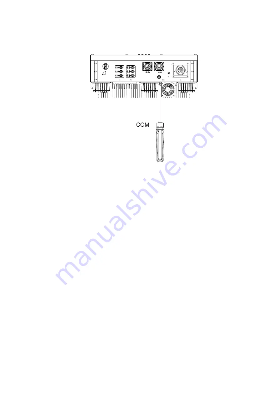
3.5.4. WIFI/GPRS communication
By the WIFI/GPRS interface, transfer the inverter power output information,
alarm information, operation state to the PC terminal or local data acquisition device.
Figure 3-11 install WIFI/GPRS module
Remark:
1) COM port, PIN3:A, PIN4:B.
2) For how to monitor system through WIFI/GPRS, please refer to the module user manual in detail.
3.6 Starting the Inverter
Before turn on the inverter, please confirm:
1) Three phase five wires (PE/L1/L2/L3/N) cable correctly connected to the inverter AC side through AC
circuit breaker;
2) The DC cable connected correctly to the inverter DC side through DC circuit breaker, please be attention
to the cable connected to the two string correctly and it’s polarity;
3) The unused terminals are covered.
Starting the inverter:
Step1
: Close the DC and AC circuit breaker;
Step2
: If the solar panels provide enough energy, the power module will work and the LCD panel will be.
lit;
Step3
: In case you are starting the inverter for the first time, the inverter needs to be commissioned.
Commissioning is described on page 17, chapter 4.3;
Step4
: Then the inverter will turn into self-check mode and the LCD panel will display the remaining. Time.
of connecting simultaneously;
Summary of Contents for R3 Pro NAC20K-DT
Page 1: ...0...
Page 11: ...10 Figure 3 5 mounting the inverter...
Page 21: ...20 P N 422 00028 01...


