background image


17


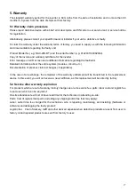
5. Warranty 

The standard warranty period for the inverter is 60 months from the date of installation and no more than 66 
months (5.5 years) from the date of shipment from factory.   
 

5.1 Warranty claim procedure 

Please report defective device with a brief error description and SN code to our service mail or service hotline 

for registration.   

Alternatively, please contact your specific dealer or installer if your unit is defective or faulty. 

To claim the warranty under the warranty terms of factory, you need to supply us with the following information 

and documentation regarding the faulty unit:    

Product Model No ( e.g. NAC-20K-DT) and the serial Number (e.g. 8122031190902002). 

Copy of the invoice and warranty certificate for the inverter. 

Error message on LCD screen and additional information regarding the fault/error. 

Detailed information about the entire system (modules, circuits, etc.). 

Documentation of previous claim/exchanges ( if applicable). 


In the case of an exchange, the remainder of the warranty entitlement will be transferred to the replacement 

device. In this event, you will not receive a new certificate, as this replacement will be noted by factory. 
 

5.2 Service after warranty expiration 

For products which are out of warranty, factory charges an on-site service fee, parts, labor cost and logistic fee 

to end-user which can be any/all of: 

On-site attendance fee: Cost of travel and time for the technician in attending on-site; 

Parts: Cost of replacement parts (including any shipping/admin fee that may apply); 

Labor:  Labor  time  fee  charged  for  the  technician,  who  is  repairing,  maintaining,  and  installing  (hardware  or 

software) and debugging the faulty product; 

Logistic fee:    Cost of delivery, tariff and other derived expense when defective products are sent from user to 

factory or/and repaired products are sent from factory to user; 


Summary of Contents for R3 Pro NAC20K-DT

Page 1: ...0...

Page 2: ...3 Technical data 5 2 4 Grid codes 6 3 Installation and startup 7 3 1 Package information 8 3 2 Installation environment 8 3 3 Installation position 8 3 4 Mounting procedure 9 3 5 Electrical connectio...

Page 3: ...tion or Tips and Tricks on specific subjects 1 3 Important safety information Read this before installing operating or maintaining the inverter Before installation Check for damage to inverter and pac...

Page 4: ...uring parallel string operation is 950V Higher voltages may result in permanent damage to the inverter The selection of PV string output should be based on the optimum utilization of the invested capi...

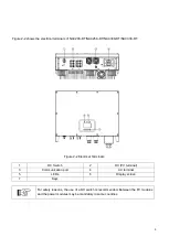
Page 5: ...T NAC33K DT Figure 2 2 Electrical Terminals 1 DC Switch 2 DC PV terminal 3 Communication port 4 AC terminal 5 LEDs 6 Display screen 7 Keys For safety reasons the use of a DC switch is recommended Betw...

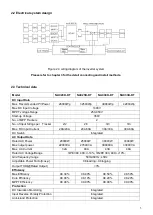
Page 6: ...ax DC Input Current 20A 20A 20A 30A 30A 30A 30A 30A DC Switch Integrated AC Output Data Rated AC Power 20000W 25000W 30000W 33000W Max output power 22000VA 27600VA 30000VA 33000VA Max AC Current 32A 4...

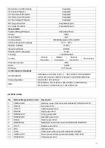
Page 7: ...0 years Certifications Standards Grid Regulation VDE AR N 4105 VDE 0126 1 1 PEA AS4777 EN50549 NB T 32004 2013 CEI0 21 IEC61727 IEC62116 IEC60068 IEC61683 Safety Regulation IEC 62109 1 IEC 62109 2 EMC...

Page 8: ...s IEC61727 28 Mexico Mexico power Grid meet Grid standards IEC61727 60HZ 29 NZ4777 New Zealand power Grid meet Grid standards NZ4777 30 Philippines Philippines power Grid meet Grid standards IEC61727...

Page 9: ...play and possible maintenance activities please install the inverter at eye level 3 Inverters should NOT be installed near inflammable or explosive items Any strong electro magnetic equipment should b...

Page 10: ...should be no less than the following value Figure 3 4 Distance required of Invertors 3 4 Mounting procedure Setp1 Drill 4 Fix 10 holes in the wall according to the dimensions Step2 Fix the wall mount...

Page 11: ...10 Figure 3 5 mounting the inverter...

Page 12: ...it value inverter will quickly disconnect with the grid If the leakage current protection device is installed externally the action current should be 300mA or higher Connect the inverter to the Grid a...

Page 13: ...itch is turned off 2 Make sure PV string polarity confirms with DC connector otherwise it will cause damage to inverter 3 Make sure the maximum open circuit voltage Voc of each PV string does not exce...

Page 14: ...re 3 9 communication interfaces Figure 3 10 RS485 in multiple series Please make sure the RS485 connecting cables not exceed 1000m Communication lines must be separated from other power lines to avoid...

Page 15: ...ter AC side through AC circuit breaker 2 The DC cable connected correctly to the inverter DC side through DC circuit breaker please be attention to the cable connected to the two string correctly and...

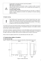
Page 16: ...cally When the next day comes the input voltage reaches the start value it will start again automatically 4 User Interface 4 1 Led and key Figure 4 1 LED display No Name Description 1 ESC Button ESC O...

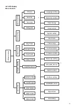
Page 17: ...ate time setting Language setting Grid info Input Password Serial number Firmware update Recovery setting String info Day Yield PV info Inverter type DSP M SW MCU H SW DSP S SW SFLASH_FS Init Clear en...

Page 18: ...r Detailed information about the entire system modules circuits etc Documentation of previous claim exchanges if applicable In the case of an exchange the remainder of the warranty entitlement will be...

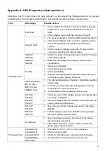
Page 19: ...If grid is ok and the problem exists still maybe the fuse in the inverter is open please call service Over Temperature INV OV Temp BST OV Temp AMB OV Temp 1 The internal temperature of inverter is hig...

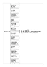
Page 20: ...uSwAcOCP SwOCP_PV1 4 HwOCP_BST1 4 UHwOCP_BST HwBusOVP uHwBusOVP BusUVP BusOVP PLL fault BusVolt_Ublc IacRms_Ublc VacRms_Ublc DciOCP GFCI 30mA GFCI 60mA GFCI 150mA GFCI 300mA GFCI 5 times uHw_GFCI Fan...

Page 21: ...20 P N 422 00028 01...
Reviews: