background image

Air Mag. M.W. II Features Explained

Adjusting the Console

1.  Adjust the console display to suitable angle for easy  

viewing by rotating the console itself with both  
hands evenly as shown.

2.  You can also change the console up side down for easy viewing when needed  

by rotating the console with both hands evenly as shown .

• 

Fold down or upward the displayed screen slowly.

• 

Rotate the console clockwise ( or anti-clockwise ) carefully. 

• 

Fold up or downward the displayed screen slowly as required.

Exchanging the Grip Handle

1.  Use your thumb & index finger of one hand to grasp &  

pull the locking sleeve as shown.

2.  Attach the plug head of selected handle into the locking socket  

and release to secure the handle attachment properly.

3.  Repeat the other side handle with same procedures

Locking

Sleeve

Plug Head

1

2

3

Adjusting the Resistance

1.  This Air Mag M.W. features a speed independent  

( 14 levels adjustable ) system.

2.  The harder you pull, the more resistance you will feel. 

As you put more efforts into your pulling, you will go faster,  
produce more watts and burn more calories.   
But it is more important to ski for a longer time than to ski harder. 

3.  The resistance is controlled by a magnet mechanism,  

which is moved closer or further away from the air fan  
wheel assembly – the closer the magnet is to the fan wheel the harder of 
resistance occurred.

4.  The magnet is controlled manually, by moving the dial lever.
5.  The resistance levels goes from 1 = easy to 14 = hard.

Dial 

Lever

14

1

2

Summary of Contents for 702011

Page 1: ...INSTRUCTION MANUAL PLEASE READ THIS INSTRUCTION MANUAL BEFORE YOU BEGIN ASSEMBLY ReNegaDE DESCRIPTION CODE VERSION ReNegaDE Air Mag M W 貳 702011 20211001 M W 貳 ...

Page 2: ...embly instructions 05 how to attached the air mag m w II on wall 11 how to take care of your air mag m w II 13 troubleshooting 13 air mag m w II features explained 14 exercising with your air mag m w II 16 exploded diagrams and parts list 22 your warranty 24 ...

Page 3: ...uncontrolled return ensure there is free space around the product You may want to store this product away to save space be aware of moving mechanical parts which could cause injury To prevent shock keep all electical components such as the console motor cord and switch away from water Do not use any accessories that aren t specifically recommended by the manufacturer these might cause injuries or ...

Page 4: ...ixings are tight before use Always replace damaged worn components with original parts from the manufacturer Protect the environment by not disposing of this product with household waste Check your local authority for recycling advice and facilities Europe only This appliance is not intended for use by persons including children with reduced physical sensory or mental capabilities or lack of exper...

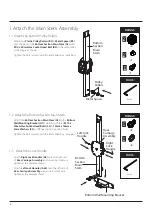
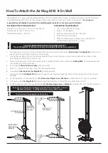
Page 5: ...t the right way up 4 Unpack the carton Make sure you have the following parts Tools and Consumables 5 Allen Key 8mm 6mm and 5mm Part No G1 Bottom Section Main Stem x 1 Part No C2 Top Wall Mounting Bracket x 1 Part No H2 Top Section Main Stem x 1 Fixings Part No S3 M8 x 30mm Hex Socket Head Bolt x 2 Part No B1 Elastic Cord x 2 Part No H1 Bottom Wall Mounting Bracket x 1 Part No A28 Left Lock Handle...

Page 6: ...Bolts S4 10mm x 18mm x 2mm Washers S5 with finger tight in position firstly Tighten the bolt securely with the 8mm Allen Key provided Bottom Section Main Stem Pulley Rollers Metal Spacer FIXINGS FIXINGS x 2 FIXINGS TOOLS 8mm x 1 x 1 6 FIXINGS FIXINGS x 3 FIXINGS TOOLS 8mm x 3 Left Lock Handle Rear Carriage Assembly Bottom Wall Mounting Bracket 1 3 Attach the Lock Handle Attach Right Lock Handles A...

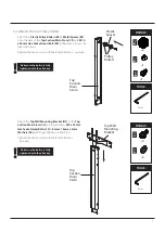
Page 7: ... same order as the diagram shown Tighten the bolt securely with the 8mm Allen Key provided Attach the Top Wall Mounting Bracket H2 to the Top Section Main Stem C2 carefully with two M8 x 30mm Hex Socket Head Bolts S3 8mm x 16mm x 2mm Washers S6 with finger tight in position firstly Tighten the bolt securely with the 6mm Allen Key provided Make sure the bolts are fully tightened with the allen key ...

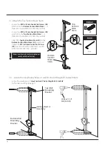
Page 8: ...Stem Loosen four M10 x 35mm Socket Set Screws C8 attached on the Bottom Section Main Stem 3 4 threads with provided 5 mm Allen Key carefully Loosen four M10 x 35mm Socket Set Screws C8 attached on the Top Section Main Stem 3 4 threads with provided 5 mm Allen Key carefully Attach the Top Section Main Stem C2 to the Bottom Section Main Stem G1 evenly and tighten the M10 x 35mm Socket Set Screws C8 ...

Page 9: ...ided Pull the right side Lock Handle A3 and raise the Air Mag M W up to the top position of main stem and engaged Fixing Bracket FIXINGS FIXINGS x 4 FIXINGS TOOLS FIXINGS FIXINGS x 4 FIXINGS TOOLS 2 1 Remove the metal posts from the back of the Air Mag M W Loosen the four M8 x 60mm Hex Socket Head Bolts from the two metal posts as shown Note The four Hex Socket Head Bolts four Plastic Spacers and ...

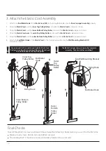
Page 10: ... diagrams shown 4 Wrap the Elastic Cord over the outer Top Pulley Roller and route the Elastic Cord as diagrams shown 5 Wrap the Elastic Cord over the outer Bottom Pulley Roller and route the Elastic Cord as diagrams shown 6 Attach the End Metal Hook of the Elastic Cord to the Fixing Hook welded on the Wall Mounting Bracket H2 properly as shown 1 2 3 4 Inner Bottom Pulley Roller Inner Top Pulley R...

Page 11: ...ly 5 Drill a 1 4 diameter hole 2 deep at each mark on wall carefully 6 Complete the Elastic Cord Air Mag M W assembly properly 7 Fold up the whole Air Mag M W II assembly against to the wall and align four holes on the top bracket to holes on wall carefully 8 Fit the top bracket to the wall with four 5 16 Hex Head Lag Screws Washers and tight with 13 17 wrench provided 9 Line up the whole Air Mag ...

Page 12: ...rk the center of the studs Measure the distance between them 3 Mark 4 marks on each piece of wood 1 from the top 1 up from the bottom and separate by the stud spacing in your wall 4 Drill through holes at each of these locations 5 Install the piece of wood such that the center line of the top piece is 80 above the floor and the lower piece is resting on the floor NOTE If you have a wooden baseboar...

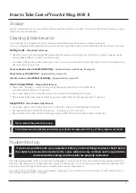
Page 13: ...hing at the handle end is intact Use a warm damp cloth to clean the whole surface of the pulling cords after every exercise if possible Check and Replace the Console AA Battery Approximately every 200 hours if equipped Check for loose Console Arm Approximately every month Clean for Dusts on Fan Wheel Assembly Approximately every month Rear Carriage Rollers Clean daily before use These rollers bear...

Page 14: ... handle into the locking socket and release to secure the handle attachment properly 3 Repeat the other side handle with same procedures Locking Sleeve Plug Head 1 2 3 Adjusting the Resistance 1 This Air Mag M W features a speed independent 14 levels adjustable system 2 The harder you pull the more resistance you will feel As you put more efforts into your pulling you will go faster produce more w...

Page 15: ...after the required position found 2 3 Right Side Lock Handle Rotating the Air Mag M W 702011 702021 models 1 Upside down Pull the left side lock handle with your left hand and rotate the Air Mag M W clockwise carefully until the stop pin engaged in position securely 2 Back to Standard Pull the left side lock handle with your left hand and rotate the Air Mag M W anti clockwise carefully until the s...

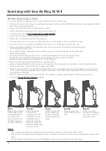
Page 16: ...iing is an extremely effective form of exercise It strengthens the heart improves metabolism as well as exercising all the major muscle groups back waist arms shoulders hips legs This M W machine offers terrific exercise for the entire body Each pull engages the legs arms shoulders and core in a down wards crunch using body weight to help accelerate the handles Each pull finishes by extending the ...

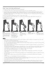
Page 17: ...intensity gradually through serval interval of 3 5 minutes in length from next ski Lower intensity levels feel like skiing in faster snow condition on flat terrain and downhill Higher intensity levels feel more like skiing in slow condition or uphill Use a intensity level setting on 8 The best all purpose intensity setting for a great cardiovascular workout is in the setting range of 6 10 Skiing w...

Page 18: ...Reverse Crossover Wood Chop Tricep Extension Overhead Boxing Cardio Cable Crossover External Rotation Cable Row Internal Rotation Front Delt Raise Mid Delt Raise Reverse Wood Chop Torso Twist Bicep Curl This Air Mag M W is not only for skierg workout but also designed for other great various functions while different positions located as shown below 18 ...

Page 19: ...ove your fitness Like any muscle in your body your heart can be strengthened by systematic physical exercise which requires an increased blood flow and heart rate You can measure your heart rate by taking a pulse reading Your heart of pulse rate corresponds directly to your exertion level and exercise efficiency To improve your fitness in a safe and effective way you need to exercise at a high eno...

Page 20: ...5 161 157 152 148 143 139 144 140 136 133 130 125 122 119 115 87 maximum heart rate TRAINING ZONE H E A R T R A T E B E A T S P E R M I N U T E The top of this bar represents 100 of maximum heart rate for each age group 155 135 111 The lower end of the training zone represents 72 of maximum heart rate for each age group AGE IN YEARS FIND YOUR OWN EXERCISE PULSE RATE RANGE BY MOVING UP THE VERTICAL...

Page 21: ...done at an intensity of between 50 60 of your estimated maximum heart rate should last about 30 minutes and can be done on most days of the week Weight loss To see a significant reduction in body fat your sessions must be a little more intense between 60 and 70 of your estimated maximum heart rate These sessions can also be performed on most days of the week for up to 30 minutes Improving Fitness ...

Page 22: ...am 22 Rear Carriage Assembly Front Section View Rear Section View C2 G1 C4 C5 C6 C7 C8 B1 B2 B3 B4 H1 S6 S3 H2 S5 S4 B2 B3 B4 A5 A7 A6 A2 A3 A12 A4 A8 A9 A10 A11 S7 A1 A12 A12 A12 A4 A8 A9 S7 S7 A7 S7 A28 C3 C3 C7 C8 ...

Page 23: ... SQ Metal Block SQ9 5 x 40 5mm 1 702011 A22 OD4 x 54mm Metal Sha 1 702011 A23 OD4 x 13 4mm Metal Sha 2 702011 A24 E Clip E3 8 702011 A25 OD4 x 17 4mm Metal Sha 1 702011 A26 OD10 x 47mm Stop Pin 1 702011 A27 Le Side SQ Metal Block SQ 9 5 x 46 mm 1 702011 A28 Le Lock Hanle OD6 x 92mm 1 702011 B1 Elas c Cord w End Hooks a ached 1 702011 B2 Plas c Pulley Roller 4 702011 B3 Metal Spacer OD15 x ID10 x 2...

Page 24: ... period we will at no additional charge provide replacement part s or repair the product at our option if it becomes defective malfunctions or otherwise fails to conform with this warranty under normal non commercial personal family or household use In repairing the product we may replace defective parts or at the option of ours use serviceable used parts that are equivalent to new parts in perfor...

Reviews: