R20UT3282ED0101 Rev. 1.1
11
2015-06-10
Chapter 6 Connectors for ports of device
Connection to each pin of the devices is possible via the connectors CN5 to CN8.
Please refer to the corresponding User Manual for available pins on the used
device.
CAUTION:
The pin headers are directly connected to the pins of the device,
therefore special care must be taken to avoid any electrostatic or other damage
to the device.
6.1
Connectors for ADC voltage supply
It is possible to apply the ADC related supply voltages via SMA connectors (CN3,
CN9; CN10 and CN11). These are directly connected (JP8 and JP10 are
bypassed) to the following pins of the device
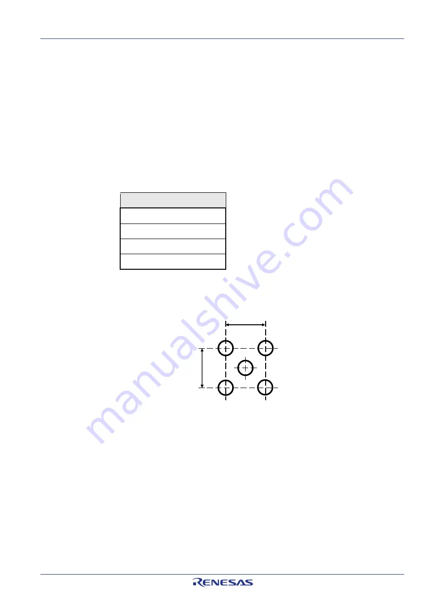
Device Port
ADC0I0
A0VREFH
ADC1I0
A1VREFH
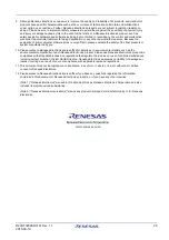
The SMA connectors are not mounted on nor provided with the boards. SMA
connectors that fit to the following mounting holes available on the board can be
mounted on the board
Figure 4 Mounting Holes for SMA Connectors
6.2
Push button for RESET
In order to issue a RESET to the device, the push-button SW1 is available.
For a correct start-up of the device the type (DPS or eVR) must be configured
correctly via JP18.
6.3
Mode Selection
The PiggyBack Board gives the possibility to configure the following mode pins
FLMD1 via jumper JP15
MODE0 via jumper JP16
MODE1 via jumper JP17
To
apply “High” or “Low” to the mode pins, the pins 1 and 2, or the pins 2 and 3 of
the corresponding jumper must be shorted, respectively.
Note:
Pin 1 is marked by a small circle.
5.1mm
5
.1
mm
Ø 1.6mm


