Emulation Adapter
System Configuration and Setup
R20UT4460EJ0110 Rev. 1.10
Page 29 of 53
Nov. 01, 2019
3.1.1
Settings for Use as a Simple Evaluation Board
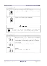
Table 3-1 and Table 3-2 show lists of the recommended settings for this system configuration.
Table 3-1 Settings for Use as a Simple Evaluation Board (Emulation Adapter)
Item
Description
Debug chip: IC1
Set an option byte. Refer to section 4.1.
Connector for external tracing:
When an emulator is in use: Connect the cable for the emulator or the 34-
pin to 14-pin conversion adapter.
When an emulator is not in use: Leave the connector open-circuit.
Set up a +5-V supply through the attached power-supply cable.
If you are using the IE850A, power can be supplied from the power-supply
cable attached to the IE850A.
An oscillator is mounted (40 MHz at shipment).
When you are evaluating the emulation adapter with a main oscillator that
has a different frequency (e.g. 20 MHz), change the oscillator.
We recommend making JP2 and JP1 open-circuit. Refer to (5) in section
We recommend making JP3 open-circuit. Refer to (6) in section 2.1.
We recommend making JP4 and 1-2 on JP5 short-circuit. Refer to (7) in
section 2.1.
We recommend making 1-2 on JP6 short-circuit. Refer to (8) in section 2.1.
Be sure to make 1-2 on JP7 short-circuit. Refer to (9) in section 2.1.
adapter: CN10, CN11, CN12, and
CN13
Connect these connectors to the base board.
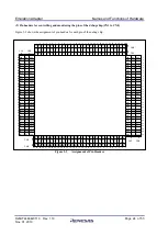
Table 3-2 Settings for Use as a Simple Evaluation Board (Base Board)
Item
Description
adapter: CN10, CN11, CN12, and
CN13
Connect these connectors to the emulation adapter.
(selecting each of the power-
supply voltages)
The voltage of each power supply is selected according to the conditions
to be evaluated or the specifications of the target device. Refer to (5) in
section 2.2.
We recommend making JP17 open-circuit. Refer to (6) in section 2.2.
We recommend making JP18 open-circuit. Refer to (7) in section 2.2.


