Emulation Adapter
Names and Functions of Hardware
R20UT4460EJ0110 Rev. 1.10
Page 17 of 53
Nov. 01, 2019
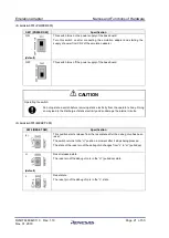
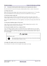
CAUTION
Unlocking the connector:
Do not press the tabs for unlocking the connector too hard as this may lead to them being
stuck in this position. Take care on this point.
(4)
Clock socket: X1
X1 is the socket for the main oscillator. A 40-MHz oscillator is mounted upon the board as shipped.
Taking the oscillation characteristics into consideration, an oscillator on the target system is not used; the
oscillator in this socket is used instead. Change the oscillator in the socket if this is required.
(5)
Jumper blocks: JP2 (CLGMD1) and JP1 (CLGMD0)
JP2 (CLGMD1)
JP1 (CLGMD0)
Specification
Open-circuit
(default)
Open-circuit
(default)
400-MHz mode
Open-circuit
Short-circuit
Settings prohibited.
Short-circuit
Open-circuit
Short-circuit
Short-circuit
(6)
Jumper block: JP3 (ICE)
JP3 (ICE)
Specification
Open-circuit
(default)
ICE pin = low
Security settings in the debug chip are enabled.
Short-circuit
ICE pin = high
Security settings in the debug chip are partially disabled.


