Emulation Adapter
Names and Functions of Hardware
R20UT4460EJ0110 Rev. 1.10
Page 22 of 53
Nov. 01, 2019
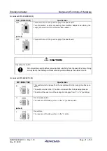
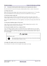
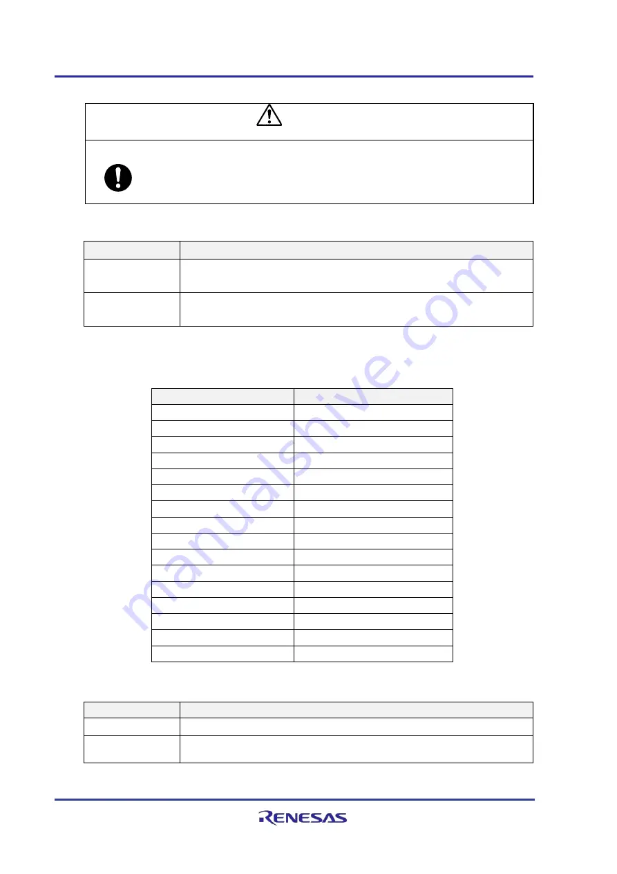
CAUTION
Operating the switch:
Do not operate a switch before removing static electricity from the operator’s body. Doing
so may lead to the discharge of static electricity and so damage the internal circuits.
(4)
Status LEDs: LED1 (3.3 V) and LED2 (5 V)
Name of LED
Specification
LED1 (3.3 V)
Illuminated: The 3.3-V power supply on the base board is on.
Not illuminated: The 3.3-V power supply on the base board is off.
LED2 (5 V)
Illuminated: The 5-V power supply on the base board is on.
Not illuminated: The 5-V power supply on the base board is off.
(5)
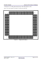
Jumper blocks: JP1 to JP16 (selecting each of the power-supply voltages)
The target power-supply voltages for each of these jumper blocks are listed below.
JP
Target Power-Supply Voltage
JP1
ADSVCC
JP2
ADSVRFFH
JP3
A0VCC
JP4
A1VCC
JP5
A2VCC
JP6
A3VCC
JP7
A0VREFFH
JP8
A1VREFFH
JP9
A2VREFFH
JP10
A3VREFFH
JP11
E0VCC
JP12
E1VCC
JP13
E2VCC
JP14
LVDVCC
JP15
SYSVCC
JP16
VCC
Each jumper block has common specifications as shown in the following table.
JP1 to JP11
Specification
Open-circuit
The target power-supply voltage is off.
1-2 short-circuit
(default)
5 V is supplied as the target power-supply voltage.


