Hardware Design Specification
ASD-B-16-0247 Rev1.3
Page 32 of 105
September 8, 2017
RTK00V2XRC7746SFS
3.10
Debug Interface
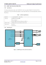
The JTAG connector can be found in the debug sub board including CPU Debug connector, JTAG debug connector and MCU
JTAG connector through 26 pin FPC (CN4) connector.
3.10.1
CPU debug
3.10.1.1
Specifications
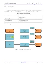
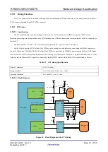
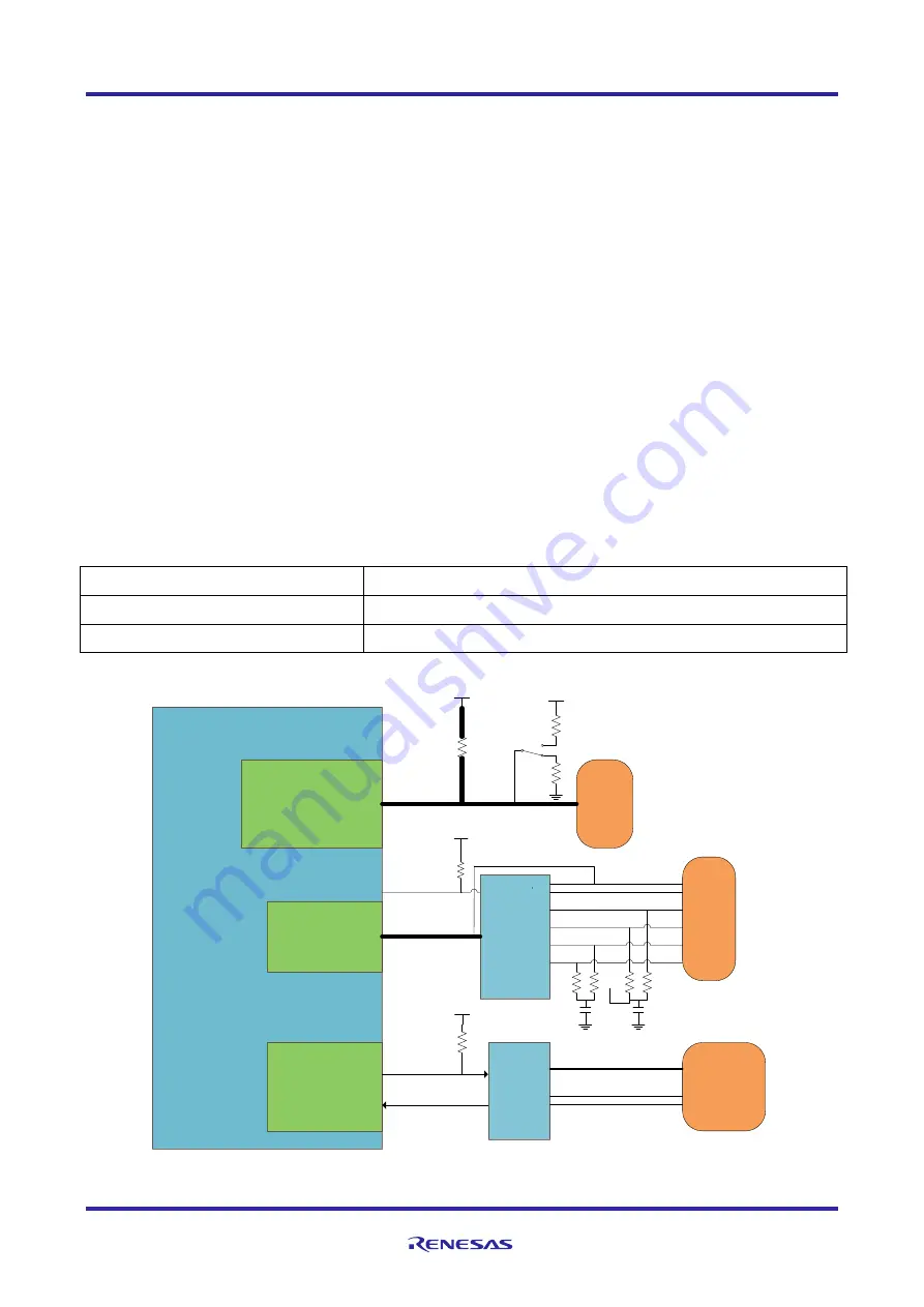
The R-Car W2H incorporates three debugger interfaces: one is a 26-pin connector (DBG) incorporates ARM core and
Real-time processing core
for connection to the JTAG emulator, one USB-B connector and the third Ethernet MAC for connection to
the host PC.
The SW3 and SW12 switch 2-3 short is for normal operation and 2-1 short for CPU JTAG Debug.
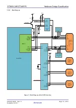
On the Tethys board, the SCIF2 of the R-Car W2H are used as debug serial interfaces by connecting the USB-B connector to
the host PC through a USB cable. The SCIF2 of the R-Car W2H is connected to the USB-B connector via the USB to UART Bridge
CP2102. The R-Car W2H incorporates the Ethernet MAC that supports 100Base-T or 10Base-T compliant with IEEE 802.3u. On the
Tethys board, the Ethernet MAC signals are connected to the RMII PHY interface (KSZ8041RNLI) manufactured by Micrel.
Table 12 CPU debug Specifications
Control Interface
CPU JTAG Debug.
Debug Interface
CN4:
IMSA-9632S-26Y801 from IRISO
operating conditions
SW3 and SW12 switch 2-1 short
3.10.1.2
Block Diagram
R-Car W2H
D1.8V
TCK, TDI, TMS
JTAG CN
CN4
49.9
DUI
TCK
TRST_N
TDI
TMS
TDO
ASEBRK
PRESETn
EtherMAC
INTRP
RMII
D3.3V
TX-
TX+
RX+
RX-
100nF
LED1
LED0
ETH_LINK
RJ45
CN3
KSZ8041RNLI
DP
DM
RXD
TXD
VBUS
USB micro-B CN
CN5
SCIF2
TX2_B
RX2_B
D3.3V
10K
4.7K
CP2102
GP5_8/SSI_SDATA7_A/IRQ8/
AUDIO_CLKA_D/CAN_CLK_D
D1.8V
TRST
4.7K
4.7K
1K
2
1
3
SW3,SW12
Figure 10 Block Diagram of the CPU debug
Summary of Contents for RTK00V2XRC7746SFS
Page 110: ...RTK00V2XRC7746SFS ...


