background image

R16UZ0016EU0102 Rev.1.2

 Page 3

Jul 28, 2021

RTKA223012DR0050BU, RTKA223012DR0060BU Demonstration Board Manual

1.  Functional Description

The RTKA223012DR0050BU and RTKA223012DR0060BU are high-side float-switching buck regulators when 
JP1 is on Pin 1 and Pin 2, and can be configured to a Buck/Boost converter when JP1 is on Pin 2 and Pin3, as 
shown on the schematic and connection diagram (

Figure 1

 and 

Figure 6

). Its input has D1 and D6 as a low-cost 

rectification (with optional full-bridge rectifier footprint). FR is a 1W fusible resistor providing input overcurrent 
protection and inrush current limiting. It also helps to absorb the input line surge energy together with DC buffer 
caps, C1 and C2. 

C1, L1, and C2 consists of the input filter that provides the energy buffer after rectification and reduces conducted 
EMI noises to the input. L2, D,2 and COUT are the buck converter components. RFB1, RFB2, CFB2, and CFB1 
provide the output feedback signal to the IC. D4 and R2 provide V

CC

 biasing current after startup to increase the 

efficiency. They can be optional for low-cost low power applications. C

VCC

 is the IC supply capacitor. 

1.1

 Recommended Equipment

▪ AC Power supply capable of generating AC voltage from 85V

AC

 to 265V

AC

 at 60Hz/50Hz, with at least 100mA 

output current capability. 

▪ Load resistor box with adjustable value of 33Ω and up, or an electronics load that can emulate a resistor load or 

current load up to 150mA. 

▪ Multimeters to measure the output voltage and current. 
▪ Power meter to measure the AC input power.

1.2

 Setup and Configuration

▪ Program the AC power supply with a voltage between 85V

AC

 and 265V

AC

 at the corresponding frequency of 

60Hz or 50Hz. 

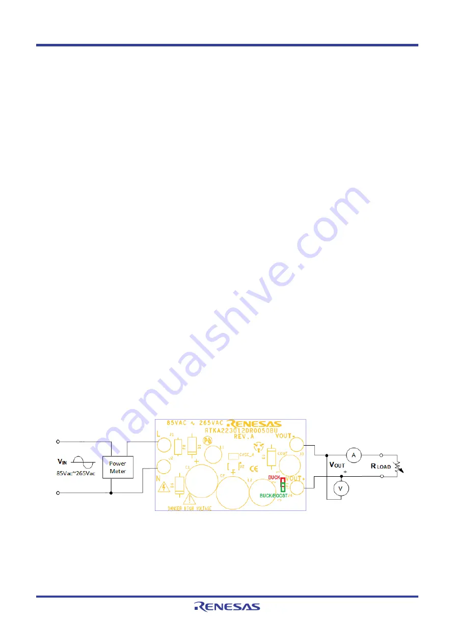
▪ While the AC power supply is off, connect the output cables of the AC power supply to the L and N terminal of 

the RTKA223012DR0050BU (or RTKA223012DR0060BU). An optional power meter can be added in between 
the AC power supply output and the input of the board.

▪ Connect the load to the output terminals VOUT+ and VOUT-.
▪ Connect a voltage meter to VOUT+ and VOUT-, and connect a current meter between board outputs and the 

load. 

▪ Turn on the AC power supply.


Figure 1. RTKA223012DR0050BU/RTKA223012DR0060BU Connection Diagram

Summary of Contents for RTKA223012DR0050BU

Page 1: ... pre compliant with conducted and radiated EMI requirements by EN55022 CISPR22 and the 1 5kV surge test by IEC61000 4 5 standard RTKA223012DR0050BU comes with a RAA223012 in a SO8 package RTKA223012DR0060BU comes with a RAA223012 in aSOT23 5 package Features Universal input range Compact PCB with low cost external components EMI compliance for EN55022 CISPR22 Surge test compliance to IEC61000 4 5 ...

Page 2: ...cription 3 1 1 Recommended Equipment 3 1 2 Setup and Configuration 3 2 Board Design 4 2 1 Layout Guidelines 5 2 2 Schematic Diagrams 6 2 3 Bill of Materials 8 2 3 1 RTKA223012DR0050BU 8 2 3 2 RTKA223012DR0060BU 9 2 4 Board Layout 10 3 Typical Performance Graphs 11 4 EMI Test Results 12 5 Ordering Information 12 6 Revision History 13 ...

Page 3: ... current after startup to increase the efficiency They can be optional for low cost low power applications CVCC is the IC supply capacitor 1 1 Recommended Equipment AC Power supply capable of generating AC voltage from 85VAC to 265VAC at 60Hz 50Hz with at least 100mA output current capability Load resistor box with adjustable value of 33Ω and up or an electronics load that can emulate a resistor l...

Page 4: ...0102 Rev 1 2 Page 4 Jul 28 2021 RTKA223012DR0050BU RTKA223012DR0060BU Demonstration Board Manual 2 Board Design Figure 2 RTKA223012DR0050BU Evaluation Board Top Figure 3 RTKA223012DR0050BU Evaluation Board Bottom ...

Page 5: ... RTKA223012DR0050BU RTKA223012DR0060BU Demonstration Board Manual 2 1 Layout Guidelines For detailed PCB guidelines see the RAA223012 datasheet Figure 4 RTKA223012DR0060BU Evaluation Board Top Figure 5 RTKA223012DR0060BU Evaluation Board Bottom ...

Page 6: ... JP1 1 2 3 D2 1 2 10 FR 1 2 1UF CVCC 1N4007 D3 1 2 1N4007 D1 1 2 560UH L2 1 2 ES1J D4 1 2 1N4007 D5 1 2 CVCC_A COUT 220UF 1 2 2 2UF C1 1 2 CFB2 470PF C3 0 47UF L1 1000UH 1 2 0 R2 15K R1 C2 2 2UF 1 2 RFB2 100K UNNAMED_2_AXIALDIODE_I14_AN UNNAMED_2_AXIALDIODE_I14_CAT UNNAMED_2_AXIALDIODE_I32_AN UNNAMED_2_AXIALDIODE_I32_CAT UNNAMED_2_AXIALRES_I25_1 UNNAMED_2_INDRADIAL_I27_1 UNNAMED_2_INDRADIAL_I27_2 ...

Page 7: ...0 FR 1 2 D2 1 2 CVCC 1N4007 D1 1 2 1N4007 D3 1 2 560uH L2 1 2 1N4007 D5 1 2 ES1J D4 1 2 1UF CVCC_A 2 2UF C1 1 2 COUT 220UF 1 2 CFB2 470PF L1 1000UH 1 2 C3 0 47UF 0 R2 C2 2 2UF 1 2 15K R1 RFB2 100K UNNAMED_2_AXIALDIODE_I14_AN UNNAMED_2_AXIALDIODE_I14_CAT UNNAMED_2_AXIALDIODE_I32_AN UNNAMED_2_AXIALDIODE_I32_CAT UNNAMED_2_AXIALRES_I25_1 UNNAMED_2_INDRADIAL_I27_1 UNNAMED_2_INDRADIAL_I27_2 UNNAMED_2_IN...

Page 8: ... L1 COIL PWR INDUCTOR TH RADIAL 5x7 1000µH 0 1A WW ROHS Bourns RLB0608 102KL 1 JP1 CONN HEADER 1x3 BREAKAWY 1x36 2 54mm ROHS BERG FCI 68000 236HLF 3 D1 D3 D5 DIODE RECTIFIER AXIAL DO 41 1000V 1A ROHS Diodes Inc 1N4007 1 D4 DIODE RECTIFIER SMD 2P SMA 600V 1A ROHS Fairchild ES1J 1 D2 DIODE RECTIFIER SMD SMB 2P 1A 600V ROHS On Semiconductor MURS160T3G 1 U1 IC 700V BUCK REGULATOR 8P SOICN 200mA ROHS R...

Page 9: ...WR INDUCTOR TH RADIAL 5x7 1000µH 0 1A WW ROHS Bourns RLB0608 102KL 1 JP1 CONN HEADER 1x3 BREAKAWY 1x36 2 54mm ROHS BERG FCI 68000 236HLF 3 D1 D3 D5 DIODE RECTIFIER AXIAL DO 41 1000V 1A ROHS Diodes Inc 1N4007 1 D4 DIODE RECTIFIER SMD 2P SMA 600V 1A ROHS Fairchild ES1J 1 D2 DIODE RECTIFIER SMD SMB 2P 1A 600V ROHS On Semiconductor MURS160T3G 1 U1 IC 700V BUCK REGULATOR 8P SOT23 200mA ROHS Renesas Ele...

Page 10: ...R16UZ0016EU0102 Rev 1 2 Page 10 Jul 28 2021 RTKA223012DR0050BU RTKA223012DR0060BU Demonstration Board Manual 2 4 Board Layout Figure 8 Top Layer Figure 9 Bottom Layer ...

Page 11: ... Figure 13 Load Regulation Buck Boost Table 1 Typical No load Power Consumption Power Supply Standby Power Energy Star 120VAC 60Hz 4 5mW 300mW 230VAC 50Hz 8 5mW 300mW 45 50 55 60 65 70 75 0 30 60 90 120 150 Efficiency Load Current mA 120Vac 230Vac 4 5 4 7 4 9 5 1 5 3 5 5 5 7 0 30 60 90 120 150 Output Voltage V Load Current mA 120Vac 230Vac 45 50 55 60 65 70 75 0 30 60 90 120 150 Efficiency Load Cu...

Page 12: ...DR0060BU Buck regulator is compliant to the conducted EMI requirements of FCC Part 15 and CISPR22 Class B 5 Ordering Information Figure 14 Line 120VAC Figure 15 Line 230VAC Figure 16 Neutral 120VAC Figure 17 Neutral 230VAC Part Number Description RTKA223012DR0050BU RAA223012 SOIC 8 Demonstration Board RTKA223012DR0060BU RAA223012 SOT23 5 Demonstration Board ...

Page 13: ...TKA223012DR0060BU Demonstration Board Manual 6 Revision History Revision Date Description 1 2 Jul 28 2021 Updated Figure 13 Completed other minor changes 1 1 Jun 25 2021 Updated Schematics Updated Bill of Materials Updated top photos 1 0 Mar 10 2021 Initial release ...

Page 14: ...RTY RIGHTS These resources are intended for developers skilled in the art designing with Renesas products You are solely responsible for 1 selecting the appropriate products for your application 2 designing validating and testing your application and 3 ensuring your application meets applicable standards and any other safety security or other requirements These resources are subject to change with...

Reviews: