RZ/A2M CPU Board RTK7921053C00000BE
2. Function specifications
R20UT4397EJ0100 Rev.1.00
2-3
2018.10.11
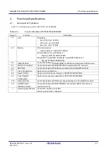
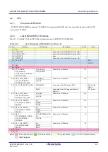
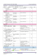
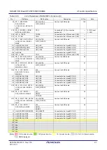
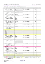
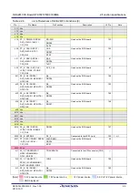
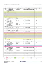
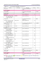
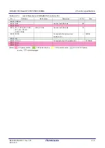
Table 2.2.2
List of Selections of RZ/A2M Pin Functions (2)
U1 Pin
Pin name
Pin Function
Description
J2 pin
Note
A19 PE_1 /
ET0_RXD0/RMII0_RXD0 /
VIO_D7 / RxD2 / POE8 /
VBUSIN1 / IRQ1
ET0_RXD0/RMII0_RXD0
Used on the SUB board
73
VIO_D7
A20 PA_4 / A20 / DV0_DATA9 /
LCD0_DATA14 /
SCI_TXD0 / MTIOC0C
DV0_DATA9
Used on the SUB board
69
LCD0_DATA14
A21 CKIO
Used on the SUB board
54
A22 Vss
B1 PK_1 /
ET1_TXD0/RMII1_TXD0 /
NAF4 / CC1_RA0 /
CAN_CLK / SSIDATA2
ET1_TXD0/RMII1_TXD0
Used on the SUB board
137
NAF4
B2 Vcc
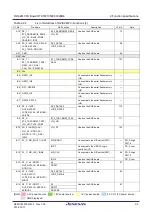
B3 QSPI1_IO1
Connected to the serial flash memory
(U2)
―
B4 QSPI1_IO0
Connected to the serial flash memory
(U2)
―
B5 RPC_RESET#
Connected to the serial flash memory
(U2)
―
B6 QSPI0_IO1
Connected to the serial flash memory
(U2)
―
B7 QSPI0_SPCLK
Connected to the serial flash memory
(U2)
―
B8 PF_5 / TxD2 /
DV0_DATA20 /
LCD0_DATA3 / MTIOC6B /
SSIFS0
DV0_DATA20
Used on the SUB board
115
LCD0_DATA3
B9 P6_3 /
ET0_TXD1/RMII0_TXD1 /
VIO_HD / TxD3 / POE0
ET0_TXD1/RMII0_TXD1
Used on the SUB board
111
VIO_HD
B10 PH_0 / AUDIO_CLK /
VIO_D1 / GTIOC4A /
MTIOC1A / CC1_RD0 /
IRQ3
VIO_D1
Used on the SUB board
105
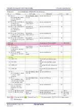
B11 PL_3 / MD_BOOT1 / IRQ7
MD_BOOT1
Connected to the DIP switch (SW1)
― PD_0: High
SW1-4
IRQ7
Connected to the USB CC logic
controller (U7)
PD_0: Low
B12 PL_1 / MD_CLK / IRQ5
MD_CLK
Connected to the DIP switch (SW1)
48 PD_0: High
SW1-2
IRQ5
Used on the SUB board
PD_0: Low
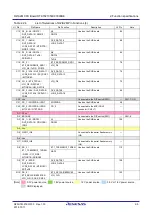
B13 P8_3 / A3 / DRP21 /
DV0_DATA14 / MTIOC6A /
GTIOC3A
A3
Used on the SUB board
97
DRP21
B14 PF_2 / TxD3 /
DV0_DATA17 /
LCD0_DATA6 / MTIOC7C /
MISO1
DV0_DATA17
Used on the SUB board
93
LCD0_DATA6
B15 P8_7 / A7 / DRP17 /
DV0_DATA10 / RSPCK0 /
SSIBCK3
A7
Used on the SUB board
87
DRP17
RSPCK0
[Note] : 3.3V power source, : 1.8V power source, : 1.2V power source, : 3.3V or 1.8V power source,
: GND displayed.

