RZ/A2M CPU Board RTK7921053C00000BE
3. Operation specifications
R20UT4397EJ0100 Rev.1.00
3-15
2018.10.11
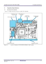
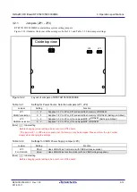
Table 3.2.3
Switches Mounted on RTK7921053C00000BE
No.
Function
Note
SW1
System setting DIP switch
For details, see Table 3.2.4.
SW2
Reset switch
For details, see section 2.8.
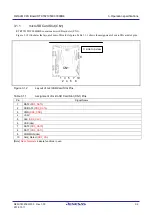
Table 3.2.4
Functions of System Setting DIP Switch (SW1)
No.
Setting
Function
SW1-1
MD_CLKS
OFF
MD_CLKS=
”
H
”
Activates SSCG.
ON
MD_CLKS=
”
L
”
Deactivates SSCG.
SW1-2
MD_CLK
OFF
MD_CLK=
”
H
”
Sets the EXTAL input frequency to 20 to 24 MHz.
ON
MD_CLK=
”
L
”
Sets the EXTAL input frequency to 10 to 12 MHz (Setting prohibited).
SW1-3
MD_BOOT2
OFF
MD_BOOT2=
”
H
”
Boot Mode
MD_BOOT[2:0]
Boot Device
0 (B'000)
Memory connected to the CS0 space (Bus width:
16 bits)
(Setting prohibited)
1 (B'001)
eSD
2 (B'010)
eMMC (Setting prohibited)
3 (B'011)
Serial flash memory connected to the SPIBSC
space (3.3V)
4 (B'100)
OctaFlash connected to the SPIBSC space
(1.8V)
5 (B'101)
HyperFlash connected to the SPIBSC space
(1.8V)
6 (B'110)
OctaFlash connected to the OctaFlash space
(1.8V)
7 (B'111)
HyperFlash connected to the HyperFlash space
(1.8V)
ON
MD_BOOT2=
”
L
”
SW1-4
MD_BOOT1
OFF
MD_BOOT1=
”
H
”
ON
MD_BOOT1=
”
L
”
SW1-5
MD_BOOT0
OFF
MD_BOOT0=
”
H
”
ON
MD_BOOT0=
”
L
”
SW1-6
BSCANP
OFF
BSCANP=”H”
Boundary scan mode
ON
BSCANP=
”
L
”
Normal operation (CoreSight debug mode)
SW1-7
Vss1
OFF
Vss1=
”
H
”
3.3V applied (Setting prohibited)
ON
Vss1=
”
L
”
GND connection
SW1-8
Vss2
OFF
Vss2=
”
H
”
3.3V applied (Setting prohibited)
ON
Vss2=
”
L
”
GND connection
[Note] : Initial setting
Before changing DIP switch settings, be sure to turn off the board.
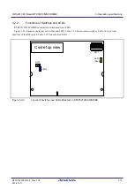
Table 3.2.5
LEDs Mounted on RTK7921053C00000BE
No.
Color
Function
LED1
Red
User LED (Lit while P6_0 output is
“
H
”
)
Green
User LED (Lit while PC_1 output is
“
H
”
)
LED2
Blue
Power LED (Lit while 5V is supplied)

