

3.1.6
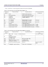
SUB Board Connector (J2) ..................................................................................................................... 3-8
3.2
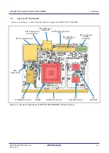
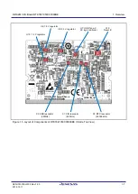
Layout of Operation Components .................................................................................................................. 3-12
3.2.1
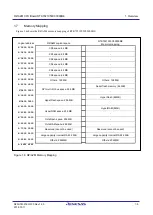
Jumpers (JP1 - JP3)............................................................................................................................... 3-13
3.2.2
Functions of Switches and LEDs .......................................................................................................... 3-14
3.3
Dimensions .................................................................................................................................................... 3-16
Appendix 1 RTK7921053C00000BE Connection Diagram ........................................................... Appendix 1-1
Appendix 2 RTK7921053C00000BE Component Installation Diagram ......................................... Appendix 2-1


