RZ/A2M CPU Board RTK7921053C00000BE
3. Operation specifications
R20UT4397EJ0100 Rev.1.00
3-3
2018.10.11
3.1.2
MIPI CSI-2 Connector (CN2, J1)
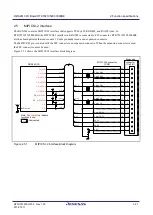
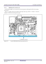
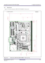
RTK7921053C00000BE contains an MIPI CSI-2 connector (CN2). Moreover, this pattern allows to mount a connector
(J1).
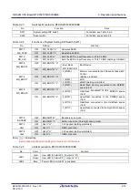
Pins 30 to 16 of the connector (NC2) are connected to pins 1 to 15. Pins 1 to 15 of the connector (J1) are connected to
pins 30 to 16 of the connector (CN2).
When using a device that cannot be connected to the connector (CN2), it is possible to create a conversion connector
via the connector (J1) to connect the device to the connector (CN2).
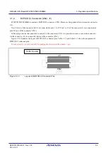
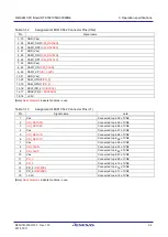
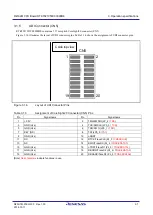
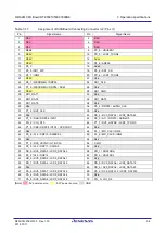
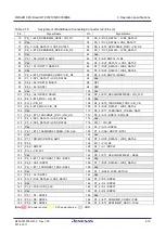
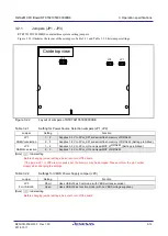
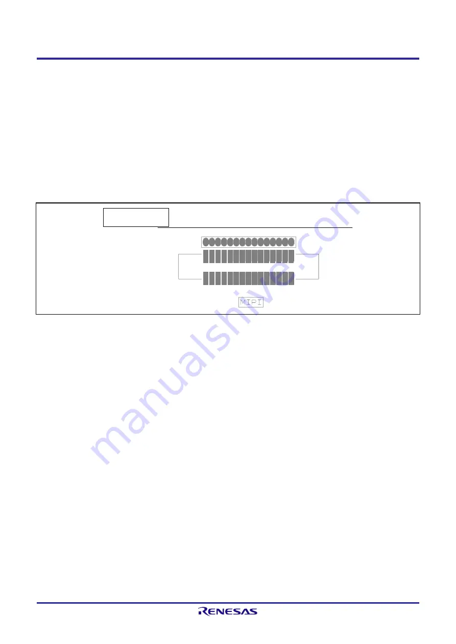
Figure 3.1.3 illustrates the layout of MIPI CSI-2 connector pins. Table 3.1.2 and Table 3.1.3 show the assignment of
MIPI CSI-2 connector pins.
If connector (J1) is used, be careful for keeping the direction of the number 1 pin.
Figure 3.1.3
Layout of MIPI CSI-2 Connector Pins
C side top view
1
15
16
30
CN2
J1
1
15

