1.800.627.4499
32
Integral Indirect Gas-Fired Heat Module
OPTION
5.7 INSTALL SUPPLY AIR TEMPERATURE SENSOR
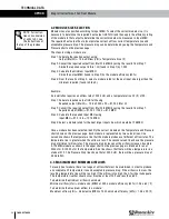
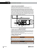
The Supply Air temperature sensor is factory-wired to the Integrated Programmable Controller
but the sensor must be installed in the SA ductwork downstream of the gas heat module. The
temperature sensor should be installed between 4 and 6 feet from the unit in the SA ductwork
to control the temperature output of the gas heat module.
The Supply Air temperature sensor is shipped in the low-voltage side of the unit electrical box.
5.8 INSTALL GAS SUPPLY PIPING
5.8.1 Installation of Gas Piping
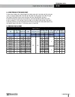
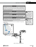
All components of this or any other gas-fired heating unit must be leak-tested prior to plac-
ing the unit into operation. A soap and water solution or other non-corrosive leak detection
fluid should be used to perform this test. NEVER test for gas leaks with an open flame.
WARNING
When leak testing at pressures equal to or less than 14 inches WC [3.5 kPa], first close the
field-installed shutoff valve to isolate the unit from the gas supply.
WARNING
INSTALLATION
5.6 MODULE INSTALLATION REQUIREMENTS
The heat module is installed on the positive pressure side of the ERV air blower. The air
throughput must be within the CFM range marked on the module rating plate.
Ductwork should be mechanically fastened to the unit. Joints should be sealed with high
temperature silicone caulking or high temperature tape to prevent leakage of circulating air. All
outdoor module duct connections must be weathertight to prevent rain and snow from entering
the ductwork. Support all ductwork securely. DO NOT rely solely on module duct connections
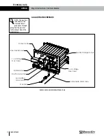
for support. Provide removable access panels in ductwork immediately downstream of the heat
module to allow for inspection of the heat exchanger. These openings should be large enough to
observe smoke or reflected light inside the casing to inspect the heat exchanger for leaks and to
check for hot spots on the heat exchanger due to poor air distribution or insufficient air volume.
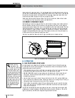
Attach covers so as to prevent air leakage. See figure below.
FIGURE 5.6.0 INSTALLATION EXAMPLE
TITLE:
DESCRIPTION OF REVISION
63 MICROINCH MINIMUM
DATE:
RenewAire LLC
SCALE:1:30
SIZE
DWG. NO.
DATE
-
-
-
BY
MATERIAL:
SURFACE FINISH =
SHEET 1 OF 1
DO NOT SCALE DRAWING.
DATE:
-
LEVEL
TOLL FREE: (800) 627-4499
DN-3-IN GH INSTALLATION EXAMPLE
--
-
APPLICABLE STANDARDS: DIM.
CHECKED BY:
--
CAH
3
REMOVE ALL BURRS, BREAK
DRAWN BY:
SEE BILL OF MATERIAL
FINISH:
A
SHARP EDGES.
FEB19
AND TOL. ANSI Y14.5
10/29/18
DN IN GH Installation
UNLESS OTHERWISE SPECIFIED,
DIMENSIONS ARE IN INCHES.
TOLERANCES:
LINEAR 0.015
HOLE SIZE 0.005
ANGULARITY
4510 Helgesen Dr.
Madison, WI 53718 USA
TEL: (608) 221-4499
FAX: (608) 221-2824
SEE BILL OF MATERIAL
Roof Deck
Combustion Air
Intake Hood
Combustion Air
Flue Exhaust Vent
Access Panel
in SA Duct
Gas Heat Module
Condensate Drain Tube
Gas Pipe Connection
Supply Air
Duct
Outside Air
Duct
Return Air
Duct

