1.800.627.4499
40
Integral Indirect Gas-Fired Heat Module
OPTION
6.6.2 Shutdown After Unit Start-Up
u
Restore any controller settings that were changed for testing purposes.
u
Disable any call for heat signal from the Integrated Programmable Controller by going in the
Service Menu > Unit Type. Change Enable Heat to NO. This will prevent the controller from
providing a call for heat signal when the unit is next started-up.
u
Disable the unit controller by going in the Main Menu > Unit Enable and changing the setting
to OFF. This will prevent the unit from activating other systems prematurely when the unit is
next started-up.
u
Turn OFF the electrical disconnect switch for the DN-Series unit.
u
Turn OFF the gas supply valve.
u
Check for tools or debris that may have been left in the unit and then replace the vestibule
cover and close the cover on the electrical panel. This will provide additional protection from
accidental exposure to high voltage wiring.
6.6.3 Configuring the Controller for Normal Operation
The gas heat module is normally left Enabled (Service Menu > Unit Type) with the gas supply
ON, unless the disconnect switch on the DOAS is turned OFF. Whenever the disconnect switch
is ON, the gas heat module also has power and will try to light whenever there is a call for heat
from the controller. As a safety measure, when power to the DOAS is turned off, the gas supply
valve is also to be turned off.
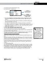
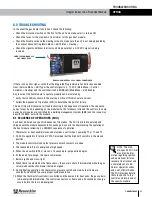
In order for the controller to provide a call for heat, several controller menu items must be
configured.
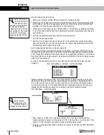
Hardware Settings: Enable Heat: YES. This setting tells the controller that there is a heating
device installed and that the controller should manage the operation of the heating device. If
this setting is left NO, the controller will not provide any control signals, Unit Status screens
or Control Variable screens for heating. When Enable is changed to YES, the controller will
manage the heat function according to the settings in the Control Variables screens.
u
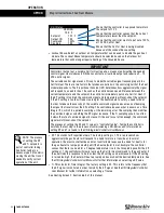
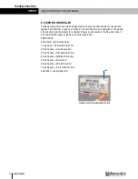
Type: always 0–10 VDC. This is the default setting. This is the signal that the gas heat
module controller responds to. If the signal is 0 VDC, it means there is no call for heat. If the
signal is 10 VDC, the heater controller will respond with maximum output.
u
Setpoint: usually adjustable, which is the default. Choices for this item are either Adjustable
or OA Reset.
NOTE: Sample
screens show the
default settings, as
shipped from the factory.
NOTE: Information
outlining the normal
sequence of opera-
tion and a wiring diagram
for the control system
supplied with each module
are provided in this manual
and with the information
package shipped with the
unit.
Path: Service Menu > Unit Type > Hardware Settings
HARDWARE SETTINGS
Enable HGRH:
YES
Enable Heat:
YES
Enable Recirc:
YES
Enable Defrost:
YES
Enable Cool:
YES
Path: Main Menu > Control Variables
HEATING SCREEN 2
HEATING SCREEN 1
Control Variables
Control Variables
Control
Return Air
Setpoint
75.2˚ F
Type
0 - 10 VDC
0-10 VDC Adjustable
Ti
30
HEATING
HEATING
Lockout Above 70.00 F
KP
1.0
Setpoint
Adjust
OPERATION

