• Do not connect the product to the power supply immediately after it has
been transferred from a cold room into a warm one (e.g., during transport).
The condensation that forms might destroy the device. Moreover, there is
danger of electric shock!
Allow the device to reach room temperature before switching it on. Wait
until the condensation has evaporated. This might take several hours.
Only after this should it be installed, connected to the mains supply and
put into use.
d) Handling, operation
• Never overload the product. Observe the maximum connected load speci-
fied in the chapter “Technical data”.
• This product should never be touched or operated with wet hands. There
is a risk of a life-threatening electric shock!
• Never pour any liquids above or next to the product. You run the risk of
causing a fire or a fatal electric shock!
If any liquid has still managed to enter the device, immediately turn off the
mains supply at all poles (turn off the automatic circuit breaker or remove
the fuse, then switch of the residual current operated circuit breaker of
the associated circuits). Contact a specialist. Do not use the product any
longer.
• Use the product only in a temperate climate, never in a tropical climate.
• Do not use the product if it is damaged. There is a risk of a life-threatening
electric shock!
• If it can be assumed that safe operation is no longer possible, the product
must be turned off and precautions must be taken to ensure that it is not
used unintentionally. Do not touch the product or any device connected to
it.
First switch off the mains voltage to all poles (switch off the connected cir-
cuit breaker or remove the fuse and then switch off the connected RCD).
• Safe operation can no longer be assumed if:
- the product shows visible signs of damage
- the product does not work at all or works poorly (leaking smoke or a
smell of burning, audible cracking noises, discolouration to the product
or the adjacent surfaces)
- the product was stored under unfavourable conditions
- it was exposed to heavy loads during transport
Preparations for connection and installation
• The device must be voltage-free during installation and connection.
Switch off all the poles of the mains cable by removing the corresponding fuse or
switching off at the circuit breaker. Then, also switch off the associated ground fault
circuit interrupter (breaker). Secure it against unauthorised reconnection, e.g., with
a danger sign.
• Check that the mains leads are without current, e.g., by means of an appropriate
tester.
• Select an appropriate installation location.
To ensure the room temperature controller functions without fault, it must be in-
stalled so it is not close to heaters, windows, doors, air discharge openings, etc.
Also keep the room temperature controller out of drafts.
Do not mount the room temperature controller behind furniture or curtains.
Because the exterior walls of a building are generally colder than the walls in the
interior of the building (depending on the building insulation), the room temperature
controller should not be mounted there.
Wall heaters work with air convection. Thus, warm air rises from the heater, cools
slowly and sinks back down on the other side of the room. Therefore, an ideal loca-
tion for installing the room temperature controller is on the wall opposite a heater;
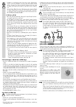
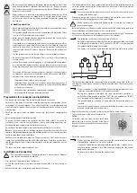
see figure.
The ideal installation height is approx. 1.5 m.
Installation and connection
Pay attention to the chapter “Safety instructions” and the chapter “Prepara-
tions for connection and installation”.
• First, switch off the mains voltage to all poles.
• Pull off the control knob of the room temperature controller; it is only loosely at-
tached.
• Remove the two cross-head screws and remove the cover.
• The bottom plate with the room temperature controller can be installed directly on
an in-wall power socket via the fastening holes using screws (distance between
holes/screws 60 mm).
Fasten the room temperature sensor in such a way that the on/off switch is
located at the bottom right.
Depending on the wall surface, the room temperature controller can also be se-
cured to the wall with appropriate screws and wall plugs.
Make certain when drilling and tightening the screws that no cables or
pipes are damaged!
Before installation, run the power cable and the connection cables to the load to be
connected through the opening next to the screw terminals.
• Now connect the mains cable and the connection cable with the load. The number
of the contact allocation can be found next to the screw terminal.
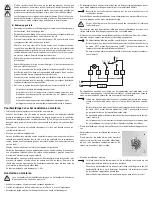
The following circuit shows the connection of a heater.
During later operation and when the room temperature controller is switched
on (sliding switch in position “ON”), the heater (“LOAD”) is activated when
the temperature falls below the set value.
The heater is switched off again when the desired temperature is reached.
6
5
1
3 2
+ °C
OFF ON
LOAD
L
N
The dashed lines indicate the connection of the integrated control light. In the cir-
cuit diagram shown above, the control light is activated when the electric load is
switched on.
If an air conditioner is to be controlled with the room temperature controller,
it must be connected to terminal 3 (instead of terminal 2).
During later operation and when the room temperature controller is
switched on (sliding switch in position “ON”), the air conditioning (“LOAD”)
is activated when the temperature exceeds the set value.
The air conditioning is switched off again when the desired temperature is
reached.
To avoid too frequent or quick successive switching processes, the air con-
ditioning should have a protection circuit.
• Replace the cover correctly and secure it with the two fastening screws.
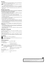
• The rotating range of the control knob can be
limited.
To do this, you can move the two small white
plastic pins (see circle on the right of the figure)
located in the holes around the rotational axis to a
different location.
• Put on the control knob again.
Always pay attention to the correct position; the control knob can only be
attached to the rotational axis in one orientation.
If you have limited the rotation range with the plastic pins, it may be neces-
sary to rotate the rotational axis a little further by hand so that the control
knob can be attached.
Do no use force when attaching the control knob!


