background image

EN


10


MU1H-0472GE23 R1020


V2.0 / 16.08.2017


Remote 

access


If a network node is accessed by a


master, the symbol “

ɔ

” is displayed.


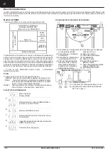
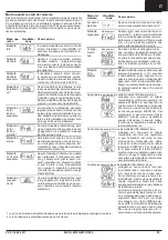
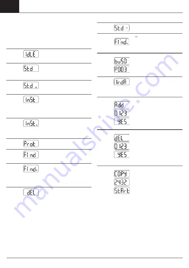
Operating modes and system states


There are various different operating modes, some of which are set 

by pressing a key on the network node, some of which are automatic 

or are set by means of a connected PC and the commissioning soft- 

ware ACT26. The current version of the commissioning software


System 

state


Display  Note


ACT26 must be available for this. The respective operating  mode 


is shown on the display:


High-speed example


mode


If all network nodes have their receives 

switched on constantly, so that all new 

data can be exchanged immediately


Operating


mode


Display  Note


within the network, this is  indicated 

by two dots in the upper section of the


Idle mode 

This is the mode of the network node 

on  delivery.  It changes to installation 

mode after the MODE key has been 

pressed somewhat longer (> 2 sec.).


Bus 

connection


LCD.


example 

If a connection to the bus is set up, the 

bus number is displayed briefly (0=M- 

Bus) as well as the primary address set


Standard 

mode


Extended 

standard 

mode

1)


Installation


This is the normal operating mode of 

the data collector:  Telegrams  from 

the registered metering devices are 

received, saved and repeated in the 

network.


The receiver is continually active and 

thus makes fast communication pos- 

sible. This mode is started  manually 

using the ACT26 service tool.


The wireless network is built up auto-


IrDA-Mas- 

ter mode


for this bus.


In the example the network node with 

primary address 03 was connected to 

the M-Bus.


This mode is started by pressing the 

MODE key briefly (< 0.5 sec.). It signal- 

ises that other IrDA devices can now be 

connected (in IrDA-Slave mode). This 

mode is automatically ended after 10 

seconds of inactivity.


mode

2)


Extended 

installation 

mode

2)


Protected 

installation 

mode

2)


Search 

mode


Extended 

search 

mode

2)


Delete 

mode

2)


matically in installation mode. Metering 

devices which transmit installation tel- 

egrams during this operating mode are 

registered in the network. This mode 

is started by pressing the MODE key 

somewhat longer (> 2 sec.).


The extended installation mode regis- 

ters all metering devices which trans- 

mit either installation or data telegrams. 

This mode helps if the network has 

been retrofitted. A network is not built 

up.


Like installation mode, but a connec- 

tion is only built up to devices which are 

using the same network coding.


Metering devices which have been 

entered manually or lost their wireless 

connection are synchronised again. 

This mode is activated automatically.


This search run is used to re-establish 

wireless connection to lost or manually 

entered metering devices. This mode 

can also be started manually with 

jumper 1 set (in the connector outlet) 

and by pressing the MODE key some- 

what longer.


Like installation mode, but all regis- 

tered devices which transmit instal- 

lation telegrams are not deleted, not 

registered (meter replacement).


Add 

example 

If a non-registered IrDA-capable meter-


ing device e.g. WHE467 is connected 

in IrDA-Master mode, this can be 

added in the network node. The display 

corresponds to the last 4 digits of the 

metering device (example: 20000123). 

The DISPLAY key must be pressed for 

confirmation when this appears on the 

display. The device is then registered 

and search mode is started.


Delete         example 

If a IrDA-capable metering device that


has already been registered is con- 

nected in IrDA-Master mode, this can 

be removed from the network node. 

The display corresponds to the last 4 

digits of the metering device (example: 

20000123). The DISPLAY key must be 

pressed for confirmation when this ap- 

pears on the display. The device is then 

deleted and the search mode ended if 

appropriate.


Copy 

example 

If a new network node is connected in


IrDA-Master mode (in idle mode!) all 

network data can be copied into the 

new node. The DISPLAY key must be 

pressed for confirmation when this ap- 

pears on the display. The protected in- 

stallation mode is automatically started 

in the network.


Depending on the data contents, copy- 

ing takes up to 20 minutes. Finally, 

“StArt Prot” is shown on the display of 

the new node for 1 hour. After instal- 

lation, the protected installation mode 

is started on the new network node  

as well by pressing the DISPLAY key. 

It is integrated in the network and the 

search run started automatically.


1)  is ended automatically after approx. 8 hours in the case of battery-operated network nodes.


2)  is ended automatically after approx. 8 hours.


Summary of Contents for Honeywell Home RNN5

Page 1: ...ngs und Installationsanleitung Operating and Installation Instructions Instrucciones de uso y de instalación Notice d utilisation et d installation Istruzioni uso installazione NETWORKNODE RNN5 DE EN ES FR IT ...

Page 2: ...de Deutsch 3 en English 8 es Español 13 fr Français 18 it Italiano 23 Dimensions 28 Mounting 29 EU Declaration of Conformity 30 ...

Page 3: ...örtlichen Entsorgungsstellen zu Die lokalen und landesspezifischen Vorschriften für die Entsorgung sind zu beachten Blitzschutz Soll in größeren Anlagen aus Einzelnetzwerken über M Bus ein Ge samtnetzwerk gebildet werden so ist wenn die Busleitungen außer halb des Gebäudes verlegt werden ein Blitzschutz vorzusehen Diese Anleitung ist während der gesamten Lebensdauer aufzubewahren CE Kennzeichnung ...

Page 4: ...knoten RNN5 230V haben zusätzlich noch ein RS232 Interface für die Auslesung Tasten Der Netzwerkknoten hat 3 Tasten mit folgenden Funktionen DISPLAY Taste 10 zur Umschaltung des Displays und zur Quittie rung von Fehlern MODE Taste 9 zum Ein oder Ausschalten des Installationsmodus Ist ein erweiterter Mode aktiv wird mit dieser Taste zum Standard Mode zurückgewechselt 1 Steckverbinder für M Bus Serv...

Page 5: ...rde Es findet keinNetzaufbaustatt Wie Installationsmode aber es wird nur eine Verbindung zu Geräten auf gebaut die die gleiche Netzwerkkenn zeichnung verwenden Einfügen beispielsweise Wird im IrDA Master Mode ein nicht registriertes IrDA fähiges Messgerät z B WHE467 verbunden kann dieses im Netzwerkknoten eingefügt werden Die Anzeige entspricht den letzten 4 Stellen des Messgerätes Beispiel 200001...

Page 6: ...rafik Netzan schluss Fixieren Sie die Hutmutter der Kabelverschraubung Netzanschluss Kabeltyp NYM J3x1 5mm2 EC6x Fehler 2 und 4 aufgetreten EC7x Fehler 1 2 und 4 aufgetreten Err1 Gerät wird nicht unterstützt Err2 Gerät wird nicht akzeptiert Listen sind voll z B mehr als 500 Messgeräte fremdes Geräte liefert falsche Daten oder Fehler Err3 Autorisierung ist fehlgeschlagen InstallationRS232RNN5 230V ...

Page 7: ...rie so startet er automatisch eine Depassivierungszyklus Das wird durch eine blin kende Frontleuchtdiode sichtbar gemacht Dieser Vorgang kann einige Minuten dauern Danach startet der Netzwerkknoten in den Drei Netzwerkknoten vor der Netzwerkinstallation Die Anzeigeebene A zeigt abwech selnd unterschiedliche Funkprimär adressen und Netzwerknummern entsprechend dem Auslieferungs zustand derRNN5 Vor ...

Page 8: ...ustbeheeded Lighting protection If an overall network is to be formed via M Bus from individual net works in larger systems lightning protection must be included in the planning of bus cables are to be routed outside the building These instructions must be stored for the entire service life CE marking The device corresponds to the applicable device specific European guidelines Frequency band 868 3...

Page 9: ...erating modekey MODE red the main battery by the backup battery Local network readout can take place via the M Bus interface an M Bus load The network nodes RNN5 230V have an additional RS232 inter face for readout purposes Keys The network node has 3 keys with the following functions DISPLAY Key 10 for switching over the display and acknowledg ing faults MODE Key 9 for switching installation mode...

Page 10: ... mode regis ters all metering devices which trans mit eitherinstallation ordatatelegrams This mode helps if the network has been retrofitted A network is not built up Like installation mode but a connec tion is only built up to devices which are using the same networkcoding Metering devices which have been entered manually or lost their wireless connection are synchronised again This mode is activ...

Page 11: ...After errors have beennoted they can bedeleted by acknowledging the error messages To do this change to the display level E by pressing the blue DISPLAY key repeatedly When the DISPLAY key is kept pressed for more than two seconds all the errors on the EA level are deleted If the error state occurs again the error code will reappear on the display Installation instructions Installation location Th...

Page 12: ... nodes level b and C must be checked on the last network node To quit installation mode the red MODE key on one of the network nodes must be kept pressed for two seconds The display for standard mode will appear The front LED can flash for up to another 30 seconds Then all the nodes in the network are set to standard mode M Bus Fixed con nection M Bus connection for gateway and service Network ins...

Page 13: ...irarse a la basura doméstica Instalación de pararrayos En caso deque se debacrear una red general en instalaciones gran des con una única red a través de un bus M se debe proveer una instalacióndepararrayos cuandolalíneadelbusseencuentrefuera del edificio Estas instrucciones deben ser conservadas durante toda la vida útil Marcado CE El dispositivocumplelas directrices europeas vigentes en relación...

Page 14: ...se puede leer localmente la red La red de nodos RNN5 230V también tiene una interfaz RS232 para la transferencia de datos de red en caso de suministro externo encendido sólo en caso de alimentación de red Erweiterungsmodul 13 miento MODE rojo 11 Tecla de cambio de pantalla DISPLAY azul 12 Interfaz de IrDA óptico Teclas El nodo de red tienen 3 teclas con las siguientes funciones DISPLAY Tecla 10 pa...

Page 15: ...dcuando la red se haya creado con posterioridad No se realiza conexión enred Igual al modo de instalación pero solo se establece una conexión con los dis positivos que emplean la misma identi ficación de red Se sincronizan de nuevo medidores que se hayan registrado manualmente o cuya conexión inalámbrica se haya perdido Este modo se activa de forma automática Esta búsqueda se emplea para recu pera...

Page 16: ...os por ejemplo más de 500 medidores Dispositivo externosuministradatos erróneos o errores Err3 Ha fallado la autorización Dispositivoexternosolicita usuarioycontraseña correctos Err4 Interrupción de la comunicación Corte de la conexión antes de finalizar la comuni cación Err5 Configuración errónea Nodo todavía en modo dereposo Adaptador de impulsos sinparametrizar nodos de red externos no están en...

Page 17: ...en red El nivel de indicador B muestra el número de nodos de la red ceso se puede producir también en otros modos por ejemplo en modo de instalación Conexión BusM En cada nodo de red se puede conectar un bus M de forma tempo ral o permanentes fijo sirviéndose de uno de los dos conectores para el bus M 1 El conector viene con el producto Los distribuidores de costes de calefacción por ejemplo WHE56...

Page 18: ...es blessures corporelles ou des dommages matériels peuvent se produire C est la raison pour laquelle seul du personnel qualifié peut effectuer des interventions sur ce terminal système Concernant son élimination l appareil est considéré comme un appareil électronique usagé au sens de la directive européenne 2012 19 UE et ne peut pas être éliminé avec les déchets ménagers Veuillez éliminer l appare...

Page 19: ...ique par exemple en cas de panne de réseau ou de changement de la batterie principale grâce à la batterie de sauvegarde Une lecture locale du réseau peut être effectuée avec l interface M Bus une chargeM Bus électrique Moduled extension 13 l affichage DISPLAY bleu 12 InterfaceIrDA optique Les nœuds de réseau RNN5 230V sont équipés en plus d une in terface RS232 pour la lecture des données Touches ...

Page 20: ...oit des télégrammes d ins tallation soit des télégrammes de don nées Ce mode est utile si le réseau a été créé ultérieurement Aucune créa tion de réseau n a lieu Ce mode est identique au mode d ins tallation À la différence près qu il crée une connexion uniquement aux termi naux qui utilisent les mêmes caracté ristiques de réseau Les terminaux de mesure qui ont été enregistrés manuellement ou qui ...

Page 21: ...duisez le câble Serrez les brins du câble selon le dessin Branchement sur secteur Fixez l écrou borgne dupresse étoupe Branchement sur secteur Type de câble NYM J 3 x 1 5 mm2 EC6x Erreurs 2 et 4 rencontrées EC7x Erreurs 1 2 et 4 rencontrées Err1 Le terminal n est pas compatible Err2 Le terminal n est pas accepté Les listes sont pleines par ex plus de 500 terminaux de mesure InstallationRS232RNN5 2...

Page 22: ...e automatiquement un cycle de dépassivation Ce qui est signalé par une diode avant qui clignote Cette procédure peut durer quelques minutes Ensuite le nœud de réseau se lance en mode IdLE En cas de fort refroidissement de la batterie ce comportement peut également se produire ultérieu rement dans d autres modes parexemple enmode d installation Raccordement M Bus Le M Bus peut être raccordé tempora...

Page 23: ...disposizioni locali e nazionali sullosmaltimento Impianto parafulmine Se in impianti di grosse dimensioni si deve realizzare una rete glo bale composta dalle singole retimedianteM Bus si deve prevedere un impianto parafulmini se le linee del bus vengono posate fuori dell edificio Le presenti istruzioni devono essere conservate per l intera durata di vita Marcatura CE L apparecchio rispetta le dire...

Page 24: ...raverso l interfaccia M Bus un carico M Bus si può eseguire la lettura locale della rete to di servizio del M Bus 2 Connettore per il modulodi ampliamento 3 Connettore per l alimentazio ne di tensione DC 3 6 V 4 LED per l indicazionedella tensione di rete in caso di alimentazione esterna si accende solo in presenza della tensione di rete backup DC 3 6 V 6 Campo connettori 7 Tasto Reset incassato 8...

Page 25: ...nviano telegrammi di installazione o di dati Questa modalità serve quando la rete è stata installata a posteriori Non ha luogo l attivazione dellarete Come la modalità di installazione però viene creata solo una connessione con gli apparecchi che utilizzano la stessa identificazione di rete Gli strumenti di misura che sono stati inseriti manualmente o che hanno per so il collegamento radio vengono...

Page 26: ...rori 1 e4 EC6x Si sono verificati gli errori 2 e4 EC7x Si sono verificati gli errori 1 2 e4 Err1 L apparecchio non viene supportato InstallazioneRS232RNN5 230V 40 mm 6 mm Err2 L apparecchio non viene accettato gli elenchi sono pieni ad esempio più di 500 strumenti di misura l apparecchio esterno fornisce dati errati o errori Err3 L autorizzazione non ha avuto esito positivo L apparecchio esterno a...

Page 27: ...può richiedere alcuni Installazione degli strumenti di misura Negli strumenti di misura viene attivata la modalità di installazione minuti In seguito il nodo di rete viene avviato nella modalità IdLE Incasodiforteraffreddamentodella batteriaquestocomportamento potrebbe verificarsi anche in un secondo momento in altre modalità ad esempio nella modalità diinstallazione Collegamento M Bus Prima dell ...

Page 28: ...28 MU1H 0472GE23 R1020 V2 0 14 08 2017 Dimensions in mm RNN5 STD RNN5 230V 13 4 128 184 160 31 8 9 8 57 2 50 200 57 2 50 200 100 100 ...

Page 29: ...V2 0 14 08 2017 MU1H 0472GE23 R1020 29 4 Mounting a 184 mm 100 mm Ø 6 mm b 2x 1 2 3 ...

Page 30: ...N 301 489 3 V1 6 1 2013 EN 61000 6 2 2005 EN 61000 6 2 AC 2005 EN 61000 6 2 2007 EN 61000 6 2 A1 AC 2012 2014 35EU Low Voltage Directive EN 60950 1 2006 EN 60950 1 A11 2009 EN 60950 1 A1 2010 EN 60950 1 A12 2011 EN 60950 1 A2 2013 2011 65 EU Restriction of hazardous Substances EN 50581 2012 and meets the requirements of following normative documents Normative Document Name Published Date Certifyin...

Page 31: ...301 489 3 V1 6 1 2013 EN 61000 6 2 2005 EN 61000 6 2 AC 2005 EN 61000 6 3 2007 EN 61000 6 3 A1 AC 2012 2014 35EU Low Voltage Directive EN 60950 1 2006 EN 60950 1 A11 2009 EN 60950 1 A1 2010 EN 60950 1 A12 2011 EN 60950 1 A2 2013 2011 65 EU Restriction of hazardous Substances EN 50581 2012 and meets the requirements of following normative documents Normative Document Name Published Date Certifying ...

Page 32: ...MU1H 0472GE23 R1020 V2 0 14 07 2015 184 mm 160 mm Ø 6 mm ...

Page 33: ...821 Mosbach Phone 49 1801 466 388 info de resideo com homecomfort resideo com 2020 Resideo Technologies Inc All rights reserved The Honeywell Home trademark is used under license from Honeywell International Inc This product is manufactured by Resideo Technologies Inc and its affiliates ...

Reviews: