background image


Supplementary features 


English 

95 


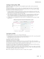
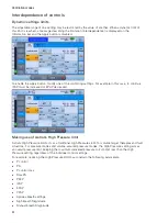
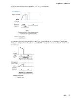
For pressure-assisted spontaneous breaths only the PS is magnified. 


For volume-controlled mandatory breaths, the volume is magnified by firstly flattening the flow shape, 
then by extending the Ti and finally by increasing the PIF. This applies to mandatory breaths in (A)CV and 
V-SIMV modes. 


Summary of Contents for Astral 100

Page 1: ...Clinical guide English ...

Page 2: ...2 Astral External Battery 12 ResMed Power Station II RPSII 12 Remote Alarm II 12 Pulse oximeter 12 Optional accessories 13 Astral Mobility bag 13 Astral SlimFit Mobility bag 13 ResMed Homecare Stand 13 Astral Table Stand 13 Aerogen nebuliser 13 ResMed Connectivity Module RCM 13 ResMed Connectivity Module Hospital RCMH 13 Using the Astral device 14 Connecting to mains power 14 Powering on the devic...

Page 3: ...atory valve 40 Connecting a double limb circuit Astral 150 only 42 Connecting a mouthpiece circuit 43 Changing the circuit selection 44 Learn Circuit 44 Accessories 48 Attaching patient circuit accessories 48 Attaching a humidifier 48 Attaching a Heat Moisture Exchange HME 50 Attaching an antibacterial filter 50 Adding supplemental oxygen 51 Monitoring delivered oxygen 53 Attaching a nebuliser 53 ...

Page 4: ...lues manually 84 AutoEPAP 86 Flow shape settings 87 Interdependence of controls 88 Dynamic settings limits 88 Making use of Astral s High Pressure limit 88 Triggering and cycling 89 Triggering with intentional leak circuits 90 Cycling with intentional leak circuits 90 Triggering with valve circuits 91 Changing the Trigger Type 92 Cycling with valve circuits 93 Triggering with mouthpiece circuits 9...

Page 5: ... alarms 115 Pressure alarms limits 115 High pressure 115 Obstruction 116 Low pressure 116 PEEP 116 Breathing circuit alarms 117 High leak 117 NV Mask Rebreathing 117 Flow sensor not calibrated 117 Circuit configuration alarms 118 Disconnection alarm 118 Oxygen alarms 118 Oximetry alarms 119 SpO2 119 Pulse rate 119 Apnoea alarm 119 Ventilation stopped alarm 119 Power alarms 120 System alarms 120 De...

Page 6: ...ifications 138 Monitoring 143 Time parameters 143 Volume and flow parameters 143 Pressure parameters 144 Other parameters 144 Accuracy of controls 145 Measurement System and Accuracy 148 Functional variants 148 Guidance and Manufacturer s Declaration Electromagnetic Emissions Immunity 149 Guidance and manufacturer s declaration electromagnetic emissions 149 Guidance and manufacturer s declaration ...

Page 7: ...settings definitions 166 Measured and calculated parameter definitions 168 Appendix B Ventilation parameters 170 Ventilation Parameters summary table 170 Ventilation displayed parameters 174 Supplementary Features 174 Supplementary Features displayed parameters 177 Appendix C Alarm parameters 179 ...

Page 8: ...structions provided in this guide Indications for use The Astral 100 150 provides continuous or intermittent ventilatory support for patients weighing more than 5 kg who require mechanical ventilation The Astral device is intended to be used in home institution hospital and portable applications for both invasive and non invasive ventilation CAUTION The Astral device is not intended for use as an ...

Page 9: ... are not available or briefly when necessary for example when changing power sources The Astral device is not intended to be operated by persons including children with reduced physical sensory or mental capabilities without adequate supervision by a person responsible for the patient s safety The Astral device is not intended to be operated by patients unless they have been given adequate instruc...

Page 10: ...ty environments may affect device performance The Astral device may experience interference in the vicinity of electronic article surveillance EAS Keep the Astral device at least 20 cm away from the EAS A note advises of special product features Notes When using Astral for long term invasive ventilation in the home due consideration should be given to relevant practice guidelines such as the AARC ...

Page 11: ...th the Astral device and include Remote Alarm II Astral External Battery ResMed Power Station II RPS II Astral Mobility Bag Astral SlimFit Mobility Bag ResMed Homecare Stand Astral Table Stand Pulse oximeter Aerogen nebuliser ResMed Connectivity Module RCM ResMed Connectivity Module Hospital RCMH Note Some accessories may not be available in all regions For a full list of accessories see Ventilati...

Page 12: ...dapter Astral 150 only 2 Handle 3 Inspiratory port to patient Provides an outlet for pressurised air to be delivered to the patient via the patient circuit Includes FiO2 sensor on the Astral 150 The FiO2 sensor is an optional accessory on the Astral 100 4 Ethernet connector service use only 5 USB connector for download to ResScan and connection of approved accessories 6 Mini USB connector for conn...

Page 13: ...gen input up to 30 L min 12 Air inlet complete with hypoallergenic filter The Astral device interface The interface of the Astral device comprises several different features described in the following image Description 1 Touch screen 2 Power source indicators AC mains power supply DC external battery or car accessory adapter or RPSII Internal battery ...

Page 14: ...utton Illuminates when an alarm is triggered and flashes when the sound is muted 5 Alarm bar Flashing red High priority alarm Flashing yellow Medium priority alarm Constant yellow Low priority alarm Touch screen The main method of interacting with the Astral device is via the touch screen The display on the touch screen changes according to the function being performed Description 1 Clinical mode ...

Page 15: ... Paediatric Circuit type Single limb with intentional leak Circuit type Single limb with expiratory valve Circuit type Double limb Circuit type Mouthpiece P1 DAY A CV Program number and program name Ventilation mode Multiple alarms are active simultaneously The highest priority active alarm is displayed first Message window Will display alarms or information Image above shows device in Standby Dis...

Page 16: ...ettings and import export data Alarms menu Configure and view alarms including alarm volume Information summary menu View therapy statistics used hours events reminder and device information Bottom bar The Bottom bar changes with the function of the device It can display buttons to Stop or Start ventilation and Apply or Cancel functions It can also display real time readings Main screen The Main s...

Page 17: ...er 4 Current pressure 5 Positive end expiratory pressure PEEP setting 6 Spontaneous triggered breath marker indicates patient triggered breath Settings bar The settings bar appears on the right hand side of the touch screen when a therapy or alarm setting has been selected for adjustment The settings bar allows the settings to be adjusted via the up and down scroll arrows or the minimum and maximu...

Page 18: ...easurement of patient exhaled gas volume may be affected by leak Patient circuit accessories The following patient circuit accessories are available for use with the Astral device Humidifier Heat Moisture Exchange HME Antibacterial filter For information on attaching and using patient circuit accessories refer to Attaching patient circuit accessories see page 48 Power accessories WARNING The Astra...

Page 19: ...I The RPSII is an external lithium ion battery that provides power when mains power is unavailable Remote Alarm II The Remote Alarm II is self powered via battery and connected to the Astral device via a cable If required a second Remote Alarm can be attached to the first Remote Alarm This enables Remote Alarms to be placed in two separate locations The Remote Alarm II can also be connected to a h...

Page 20: ...l battery or power supply unit ResMed Homecare Stand The ResMed Homecare Stand is designed to hold and move compatible ResMed ventilators and accessories between points of therapy in the hospital and limited care facilities For further information see the Homecare Stand user guide Astral Table Stand The Astral Table Stand provides an ergonomic and convenient solution for placing the Astral device ...

Page 21: ...ResMed external power supply unit to the rear of the Astral device 2 Connect the power cord to the ResMed power supply unit 3 Plug the other end of the power cord into the power outlet For further information on powering the Astral device refer to Power management see page 59 Powering on the device To power on the Astral device simply press the green power on off button at the back of the device T...

Page 22: ...al battery continues to charge Accessing Clinical mode The closed padlock indicates the device is in Patient mode To access clinical functions such as the Setup Assistant and program configurations you must enter Clinical mode Clinical mode can be accessed from any screen whether or not the Astral device is ventilating To access Clinical mode 1 From the patient home screen press and hold for 3 sec...

Page 23: ... up the device for use by a new patient The Setup Assistant prompts you to assemble components and automates testing of the circuit For detailed instructions on assembling patient circuits and other components and accessories refer to Assembling patient circuits see page 36 The Setup Assistant can only be accessed when the Astral device is in Clinical mode Note Using the Setup Assistant will clear...

Page 24: ...tach and test the circuit For detailed instructions on how to attach the circuit refer to Assembling patient circuits see page 36 When the Learn Circuit is complete you will be prompted to select your required Interface type The interface type selection is used to determine if the disconnection alarm can be turned off and also sets a suggested setting for the disconnection alarm Note If the circui...

Page 25: ...ings for the mode are displayed 10 Review and adjust the settings and alarms as required For further information on adjusting setting parameters and alarm settings refer to Adjusting patient settings see page 28 and Adjusting alarm settings see page 108 11 Press to start ventilation ...

Page 26: ...as well as Alarm mute The Big buttons mode can be switched on and off as required in either Clinical or Patient mode WARNING To prevent inadvertent alarm mute or reset do not leave the patient in contact with the device screen To enable the Big buttons mode 1 From the Main menu press Setup The Setup menu is displayed 2 Select the Patient Access tab from the Device Config menu 3 Move the Big button...

Page 27: ...he enhanced access feature enabled your screen will return to Big buttons mode once the screen locks after two minutes of inactivity Starting and stopping ventilation WARNING Always ensure that the values in the ventilation therapy and alarm settings are appropriate before starting therapy Note If using the device for the first time ResMed recommends performing a functional test before starting ve...

Page 28: ...een is locked the button is highlighted orange Unlocking the touch screen Touch the screen anywhere and follow the on screen prompts Navigating the menus The Astral device has four menus accessible via the Menu bar Each menu is further broken down into various sub menus This chapter focuses on what the menus are and their structure For information on adjusting and configuring features refer to Usi...

Page 29: ...esponse Apnoea Response Apnoea Detection Alarm Volume Alarm Level Alarm Minimum Volume Alarm Test Disconnection Alarm Disconnection Alarm Information Events Alarms Settings System Delete Device Basic Advanced Battery Charge Maintenance Available in Clinical mode only Monitors menu The Monitors menu allows you to view real time ventilation data and is comprised of three sub menus Waveforms Monitori...

Page 30: ...ttings to change the ventilation mode and related settings USB to save patient data and import export settings Device config to change the device configuration Alarms menu Display the Alarms menu to view update the individual thresholds for each alarm to trigger Real time values are displayed between the upper and lower thresholds The options available for adjustment change depending on the circui...

Page 31: ...ion therapy and alarms settings should be verified for each enabled Program Working with programs The Astral device comes factory preset with one active program Additional programs can be enabled Astral 100 provides a maximum of two programs Astral 150 provides for a maximum of four programs Programs allow for different circuit ventilation and alarm settings Programs provide convenient patient acc...

Page 32: ...P1 A CV is the current active program P2 has been enabled and is showing the factory preset mode 4 Rename the program by pressing the Rename button Within the Rename window a name for the current active program can be chosen from the list provided In the screen below the selected name DAY is highlighted Note A selected name can be removed by pressing the delete button 5 When selected the program n...

Page 33: ... Note Each program retains its own circuit configuration When switching between programs ensure you use the correct circuit as learned for that program Setting up a new program Adjustments to program settings can only be made to the current active program To make changes to settings of other programs you must first activate that program Adjustments to patient settings can be made while the device ...

Page 34: ...ill display the current active Ventilation mode will be highlighted orange Select your required Ventilation mode 4 You will be returned to the Main Settings page All changes you have made will be outlined in orange indicating a pending status until you press Apply If the mode change is cancelled you will be returned to the current active mode s primary settings page Any modifications will be disre...

Page 35: ... Main settings screen will be displayed 2 Select the setting that you want to adjust The selected setting is highlighted in orange and the Settings bar appears on the right side of the screen 3 Increase or decrease the selected setting as desired 4 If adjustments to other selected settings are required select the desired settings and repeat this process All settings that have been adjusted are sho...

Page 36: ... the Monitoring screen and a summary of critical values in the bottom bar Graphically on the Waveforms Trends screen and Pressure bar Monitoring screen The Monitoring screen displays all measured parameters in numerical form For details on the available monitoring parameters refer to the Ventilation Parameters Summary Table see page 170 Waveforms The Waveforms screen displays the last 15 seconds o...

Page 37: ...visible from other screens This permits critical ventilation parameters to be continuously monitored while performing other tasks on the Astral device Note The ventilation measures on the Bottom bar will be hidden while an action request is displayed For example Apply Cancel Trends screen The Trends screen shows the 5th and 95th percentile values as well as the median for the last 30 days for each...

Page 38: ...he Internal battery or an External battery Default On Display brightness Y Sets the brightness of the screen from Auto with a selection of five different brightness levels Default Auto Backlight timeout Y Allows the screen backlight to turn off go black if the screen has not been touched for two minutes or more and there are no active alarms Setting to Off will mean the screen back light will be p...

Page 39: ...s that are able to be adjusted by the patient are enabled Copying device settings The Astral device allows for all settings to be copied from one device to another via a USB stick Ventilation settings for all available patient programs and device configuration settings can be copied Settings can only be copied between compatible Astral devices To be compatible both devices must be the same variant...

Page 40: ...am prior to commencing ventilation To import device settings 1 Insert a USB stick into the USB connector at the rear of the device Refer to Data Management process see page 127 2 Enter Clinical mode 3 From the Main menu press Setup The Setup menu is displayed 4 Select the Settings tab from the USB sub menu The Import button will become active if there are settings from a compatible device availabl...

Page 41: ...fe Using the Service reminders When either a Preventative maintenance or Battery replacement reminder is present a reminder button is displayed in the right corner of the bottom bar Note Service reminders are only visible in Patient mode Select the reminder button to display the reminder prompt Acknowledgment of the prompt will clear the reminder prompt and reminder button The reminder button will...

Page 42: ...d or disabled in Clinical mode 1 Access Clinical mode 2 From the Main menu press Setup The Setup menu is displayed 3 Select the Reminders tab from the Device Config sub menu 4 Move the Preventative maintenance or Battery replacement reminder to ON 5 Access Patient mode Your Service reminder is now enabled ...

Page 43: ...circuit for direct measurement of exhaled volumes In this configuration the expired volume is returned to the ventilator for independent measurement Astral 150 only The Astral device does not support monitoring of exhaled volumes when used with a single limb circuit with expiratory valve The patient circuit should be arranged so as not to restrict movement or pose a strangulation risk Only use cir...

Page 44: ... valve expiratory valve integrated into the circuit 3 Double limb Astral 150 only Double limb circuit expiratory valve integrated into the adapter OR single limb circuit with intentional leak or mouthpiece circuit A Learn Circuit should be performed after any change of circuit Astral will provide accurate therapy as long as the Learn Circuit is completed Refer to Learn Circuit see page 44 for furt...

Page 45: ...stimate the patient respiratory flow and tidal volume in the presence of unintentional leak WARNING At low pressures the flow through the mask vents may be inadequate to clear all exhaled gases and some rebreathing may occur when using a single limb circuit with intentional leak Ensure the vent holes at the mask or at the ResMed Leak Valve are unobstructed Ensure the area around the vent holes is ...

Page 46: ...etting Connecting a single limb circuit for invasive use CAUTION Always set up the ResMed Leak Valve in the breathing circuit with the arrows and the symbol pointing in the direction of air flow from the Astral device to the patient For invasive ventilation since the patient s upper respiratory system is bypassed by an artificial airway device for example endotracheal or tracheostomy tube humidifi...

Page 47: ...ine is designed specifically for use with Astral ventilators To connect an Astral Quick Connect Single Limb Circuit with expiratory valve 1 Check the device is equipped with the single limb adapter otherwise change the adapter 2 Connect the air tubing to the inspiratory port on the device 3 Attach the Astral Quick Connect circuit to the single limb adapter on the device see diagram below 4 Attach ...

Page 48: ...ngle limb adapter 2 Connect the PEEP control line to the lower connector of the Astral device single limb adapter 3 Connect the air tubing to the inspiratory port of the device 4 Attach any required circuit accessories eg humidifier or filter 5 Select the circuit type and perform a Learn Circuit 6 Attach a patient interface eg mask to the connector on the expiratory valve ...

Page 49: ...led tidal volume to be accurately measured and monitored To connect a double limb circuit 1 Ensure the device is fitted with the double limb adapter otherwise change the adapter 2 Connect the ends of the air tubing to the inspiratory and adapter ports on the device 3 Attach any required circuit accessories eg humidifier or filter 4 Select the circuit type and perform a Learn Circuit 5 Attach a pat...

Page 50: ...xpiratory valve or intentional leak should be considered To connect a mouthpiece circuit 1 Check the device is fitted with a single limb leak adapter Otherwise change the adapter Note The Astral 150 can also support mouthpiece circuit using a double limb adapter 2 Connect the inspiratory limb to the inspiratory port 3 Attach any required circuit accessories eg filter 4 Select the circuit type and ...

Page 51: ...nality the Astral performs a device self test and a calibration of the FiO2 sensor if installed CAUTION To ensure optimum and accurate performance it is recommended that the Learn Circuit function be performed with every change of circuit configuration and at regular intervals not less than once every three months Do not connect patient interfaces prior to performing the Learn Circuit Patient inte...

Page 52: ...e you through a number of steps including With the patient interface disconnected from the patient connection port the Astral device will characterise the impedance of the inspiratory path With the patient connection port sealed the Astral device will characterise the total circuit compliance and then the impedance of the expiratory path After completing these steps a test result screen is display...

Page 53: ...t issue Refer to Learn Circuit Troubleshooting see page 160 for suggested actions on the error code 1 Inspect the circuit and proximal lines for disconnection or excessive leak 2 Check that the circuit is correctly connected and matches the selected circuit type 3 Check that the correct circuit adapter is installed for the selected circuit type 4 Check the module the blue membrane and sensor are p...

Page 54: ...he device for servicing by an authorised ResMed Service Centre If you choose to proceed with ventilation FiO2 alarms will be disabled An alternate method for monitoring FiO2 is required Expiratory Flow Sensor Results Icon Description Expiratory flow sensor calibration has passed Expiratory flow sensor not tested or not installed Expiratory flow sensor calibration has failed Below are general steps...

Page 55: ...the patient s upper respiratory system is bypassed by an artificial airway device for example endotracheal or tracheostomy tube humidification of the inspired gas is required to prevent lung injury Always place the humidifier on a level surface below the level of the device and the patient to prevent the mask and tubing filling with water Only use humidifiers that comply with the relevant safety s...

Page 56: ...sensor if the air is cooled to below its dew point Condensation may also form in the patient circuit and is most likely to form at high humidity settings and low ambient temperatures Condensation forming in the expiratory flow sensor may cause a loss of expiratory flow measurement and compromised therapy ie auto triggering increased PEEP and activation of the leak alarm To prevent condensation at ...

Page 57: ... prior to performing the Learn Circuit Patient interfaces include any components placed after the single circuit s expiratory valve or exhalation port or double limb circuit s Y piece eg HMEF catheter mount mask tracheostomy tube Attaching an antibacterial filter WARNING Regularly check the antibacterial filter and expiratory valve for signs of moisture or other contaminants particularly during ne...

Page 58: ...lter is mandatory if the device is to be used on multiple patients The expiratory module internal antibacterial filter expiratory flow sensor and blue membrane come into contact with exhaled gases but do not form part of the inspiratory pathway Adding supplemental oxygen The Astral device is designed to be compatible with levels of supplemental oxygen up to 30 L min At a fixed rate of supplemental...

Page 59: ...from any sources of ignition Monitor supplemental oxygen using the integrated FiO2 sensor and alarms or use an external O2 monitor compliant with ISO 80601 2 55 When operating Astral in its mobility bag do not add more than 6 L min of supplemental oxygen Astral is not designed for use with heliox nitric oxide or anaesthetic gases Do not position the Astral device on its side as this may affect FiO...

Page 60: ...sition the Astral device on its side as this may affect FiO2 monitoring accuracy Attaching a nebuliser If required a nebuliser can be used in conjunction with the Astral device ResMed recommends Aerogen nebuliser products designed to operate in line with standard ventilator circuits and mechanical ventilators without changing ventilator parameters or interrupting ventilation WARNING Always connect...

Page 61: ...xcessive pressure for prolonged periods as this can cause patient pressure injury The pulse oximeter sensor and cable needs to be verified for compatibility with Astral otherwise patient injury can result CAUTION Factors that may degrade pulse oximeter performance or affect the accuracy of the measurement include the following excessive ambient light excessive motion electromagnetic interference b...

Page 62: ...bility For information on how to use these accessories refer to the user guide that comes with these accessories Once you have attached the pulse oximeter a message will briefly display in the information bar Real time SpO2 and Pulse readings can be viewed from the Monitoring menu Notes Values from the SpO2 sensor are averaged over 4 heartbeats Included SpO2 sensor is calibrated for the display of...

Page 63: ...alarm is triggered on the Astral device For full instructions on using the Remote Alarm II see the User Guide that comes with that device To connect the Remote Alarm II to the Astral device 1 Connect one end of the alarm cable to the 3 pin input connector on the remote alarm 2 Connect the other end to the 5 pin output connector located at the rear of the Astral device CAUTION To remove the cable p...

Page 64: ...cluding Remote Alarm and oximeter the USB Stick 2 Place the Astral device carefully into the Carry Bag ensuring the handle is at the top and the screen faces the printed image on the bag 3 Secure the Astral device in place by using the Velcro strap To ensure the most secure position thread the Velcro strap through the handle and attach 4 Place the Power Supply unit and any heavy components in the ...

Page 65: ... is for carry on luggage only The carry bag will not protect the Astral device if it is put through checked baggage For your convenience at security stations it may be helpful to keep a printed copy of the user guide in the Astral carry bag to help security personnel understand the device and refer them to the following statement ResMed confirms that the Astral device meets the Federal Aviation Ad...

Page 66: ... the internal battery for mobile use Ensure the external battery is sufficiently charged before using in mobile situations WARNING Beware of electrocution Do not immerse the device power supply or power cord in water Make sure the power cord and plug are in good condition and the equipment is not damaged Keep the power cord away from hot surfaces Explosion hazard do not use in the vicinity of flam...

Page 67: ...ice 2 Before connecting the power cord to the ResMed power supply unit ensure the end of the connector of the power cord is correctly aligned with the input socket on the power supply unit 3 Plug the other end of the power cord into the power outlet Note The power cord is equipped with a push pull locking connector To remove grasp the power cord housing and gently pull the connector from the devic...

Page 68: ...evice Once the External Battery is connected to the Astral device the DC mains indicator on the user interface will illuminate WARNING Do not attempt to connect more than two external batteries Battery specific messages and alarms on the Astral device will not operate for any additional units In the unlikely event of an issue occurring with the external battery Astral will sound an alarm and notif...

Page 69: ...l battery together Connecting to an external DC power source CAUTION When using a car auxiliary adapter start the car before plugging in the device s DC adapter If the external DC power source drops to below 11V the Astral will switch to internal battery When the device is turned off while connected to the DC adapter it will continue to draw power from the external DC power source To connect DC po...

Page 70: ... available or briefly when necessary for example when changing power sources CAUTION Revert to AC mains power when the remaining capacity of the battery is low The internal battery may stop charging when ambient temperatures of 35 C or more are reached This will be indicated with a Power fault No charging alarm message The internal battery will be depleted if the device is left in storage for an e...

Page 71: ... charge levels can be accessed in one of two ways 1 Battery Indicator The capacity of all connected batteries will be added to the RunTime indicator on the Information bar of the Astral interface This may take a couple of minutes The total will be the sum of the Astral internal battery plus either one or two external batteries Under normal operating conditions the ventilator will display Total sys...

Page 72: ...nt charge level 0 100 for any batteries currently detected by the system as well as the total system charge Maintenance displays the full charge capacity and the charge cycle count for any batteries currently detected by the system Regularly check the charge level of the internal battery and any connected external batteries It is recommended to replace any batteries at 400 charge cycles ...

Page 73: ...e ventilator Press the power switch at the back of the device to turn on the device Check that the alarm sounds two test beeps and the LEDs for the alarm signal and the alarm mute reset button flash The device is ready for use when the Patient Home screen is displayed 5 Disconnect the device from the mains and external battery if in use so that the device is powered by the internal battery Check t...

Page 74: ...osen Mode settings can be accessed from Main Settings tab from the Settings menu Note Some features may not be available on your device Mode Circuit type Supplementary feature Leak circuits Valve circuits Mouthpiece circuits Apnoea ventilation Safety Vt Manual breath Sigh breath A CV P A CV P SIMV V SIMV PS CPAP S T P A C iVAPS For valve circuits only ...

Page 75: ...10 to 120 50 Paed 5 to 60 10 Ti sec When Volume Breath option is set to Ti Adult 0 3 to 3 0 1 0 Paed 0 3 to 3 0 0 6 Flow shape 100 Constant 75 50 25 100 Trigger Type Flow Pressure Trigger When Trigger Type is set to Flow double limb circuit only Adult Off 0 5 to 15 1 0 L min Paed Off 0 5 to 15 0 5 L min When Trigger Type is set to Pressure double and single limb circuit Off Very low to Very high M...

Page 76: ...iggered breath or the patient spontaneous triggered breath Spontaneous triggered breaths re schedule the next time triggered breath Both Trigger and Resp rate can be set to Off but not at the same time When Trigger is set to Off the mode name will be shown on the Information bar as PCV End of inspiration switch from inspiration to expiration is controlled by the ventilator time cycled breath Param...

Page 77: ...ff Very Low to Very High Medium Rise Time msec Min 150 to 900 200 Note Some default settings are different for Mouthpiece circuit Supplementary features Safety Vt Tidal Volume Apnoea response Sigh breath Astral 150 only Manual breath Astral 150 only The P A CV breath pattern showing one patient triggered breath amongst time triggered breaths The Safety Vt feature is turned off ...

Page 78: ...me triggered breath For spontaneous breaths The inspiratory pressure support is set using PS Inspiration is either Initiated by the patient spontaneous triggered breath Ended by the patient spontaneous cycled breath The patient is free to take any number of spontaneous breaths between mandatory breaths Parameter Setting Resp rate per min Mandatory breaths Adult 2 to 50 10 Paed 5 to 80 20 PEEP cmH2...

Page 79: ... are delivered at a set frequency and spontaneous breaths are permitted between mandatory breaths For mandatory breaths The inspiratory volume is set using Vt and is initiated by either the ventilator at a set respiratory rate the patient if the patient effort is close enough to the next scheduled mandatory breath This time is 60 of the breath period or 10 seconds whichever is less End of inspirat...

Page 80: ...s 5 to 90 Auto Auto Trigger type Flow Pressure Trigger When Trigger Type is set to Flow double limb circuit only Adult 0 5 to 15 1 0 L min Paed 0 5 to 15 0 5 L min When Trigger Type is set to Pressure double and single limb circuit Very Low to Very High Medium Rise Time msec Spontaneous breaths Min 150 to 900 200 The International ventilator standard indicates that Paediatric patient type is inten...

Page 81: ...lation mode delivering pressure supported spontaneous breaths Inspiration is either initiated by the ventilator at a set rate time triggered breath or the patient spontaneous triggered breath Spontaneous triggered breaths re schedule the next time triggered breath Set respiratory rate can be disabled End of inspiration switch from inspiration to expiration is controlled by the patient spontaneous ...

Page 82: ...8 Note Some default settings are different for Mouthpiece circuit Supplementary features Apnoea response Safety Vt Tidal Volume Manual breath Astral 150 only This graph shows PS mode with Resp rate enabled with a transition from spontaneous triggered to time triggered breaths Cycling is constrained within the limits of Ti Min and Ti Max To allow the patient sufficient time to exhale Ti cannot exce...

Page 83: ...igger is set to Off the mode name will be shown on the Information bar as T When Trigger is active and Resp rate is set to Off the mode name will be shown on the information bar as S End of inspiration switch from inspiration to expiration is controlled by the patient spontaneous cycled breath between Ti Min and Ti Max Parameter Setting Resp rate per min Adult Off 2 to 50 15 Paed Off 5 to 80 15 EP...

Page 84: ... is set to Off the mode name will be shown on the Information bar as PC End of inspiration is controlled by the ventilator time cycled breath Parameter Setting Resp rate per min Adult Off 2 to 50 15 Paed Off 5 to 80 15 EPAP cmH2O 2 to 25 5 IPAP cmH2O Adult 4 to 50 12 Paed 4 to 50 12 Ti sec Adult 0 3 to 4 0 1 0 Paed 0 3 to 4 0 0 6 Trigger Off Very Low to Very High Medium Rise Time msec Min 150 to 9...

Page 85: ...ratory triggering level is settable to optimise monitoring and alarm performance Parameter Setting CPAP cmH2O All circuits 3 0 to 20 0 5 0 Trigger type Double limb circuit Flow Pressure Trigger Double limb circuit When Trigger Type is set to Flow Adult 0 5 to 15 1 0 L min Paed 0 5 to 15 0 5 L min When Trigger Type is set to Pressure Very Low to Very High Medium Single limb circuit Very Low to Very...

Page 86: ...sure achieved during iVAPS or iVAPS AutoEPAP therapy is the sum of the EPAP and pressure support limited to 2 cmH2O below the set High Pressure limit As a result High Pressure limit can be a useful way to constrain overall therapy pressure eg during Mask NIV on page 101 The rate of increase in pressure support can reach up to 0 7 cmH2O sec The breath to breath changes in pressure support depend on...

Page 87: ...ly so iVAPS estimates it using a height approximated value of anatomical deadspace as shown in the graph below Anatomic deadspace is the amount of breath that remains in the conducting airways that does not reach alveoli and does not contribute to gas exchange Its contribution is proportional to breath rate By using alveolar ventilation as a servo ventilation target as opposed to tidal volume or m...

Page 88: ...eath resets the iBR to its background rate two thirds of Target Patient Rate Configuring iVAPS There are two ways in which you can configure iVAPS mode Adopting the recently learnt targets from any vented mode CPAP S T or PAC learns the patient s breathing pattern and calculates the target values automatically or Entering the target values manually Adopting recently learnt targets While ventilatin...

Page 89: ... select Settings 2 From the Settings menu select the Main settings tab 3 From the on screen selections press Ventilation Mode then select iVAPS 4 From the on screen selections press Review Note The Review option will only be available for selection if there is at least five minutes worth of patient data available ...

Page 90: ... Review the Learnt Targets and make adjustment to Pt Height if required Select Confirm 6 Select Apply You have now successfully configured iVAPS Note With AutoEPAP switched on the information window name is updated to iVAPS AutoEPAP ...

Page 91: ...a settable Target Va parameter and patient height Target Pt Rate should match the patient s normal breathing rate To enter the target values manually 1 From the Setup main menu select Settings 2 From the Settings menu select the Main Settings tab 3 From the on screen selections press Ventilation Mode then select iVAPS 4 Select Skip ...

Page 92: ...Ventilation modes English 85 5 From the iVAPS main settings screen select Apply iVAPS has been successfully applied ...

Page 93: ...ressure limit pressure support is sacrificed to maintain airway patency ie EPAP However pressure support will not drop below the set minimum pressure Min PS a For flow limitation EPAP will increase at a maximum rate of 0 5 cmH2O 0 5 hPa per breath b For obstructive apnoea EPAP will increase at a rate of approximately 1 cmH2O 1 hPa per second spent in inspiration on termination of the apnoea c EPAP...

Page 94: ...ters the inspiratory duration whereas with volume breath option set to Ti Inspiratory time adjusting the flow shape alters the Peak Inspiratory Flow When the flow shape is set to 100 the flow is generally constant during inspiration For decreasing percentages the flow starts at the peak flow and declines to approximately the percentage setting of this value at the end of inspiration To select betw...

Page 95: ...eased or EPAP decreased Making use of Astral s High Pressure limit Astral s High Pressure limit acts as a traditional High Pressure alarm for volume target therapies and fault situations For pressure modes and volume assured pressure modes the High Pressure setting acts as an overall pressure limit keeping the maximum delivered pressure to 2 cmH2O less than the High Pressure setting regardless of ...

Page 96: ...nspiratory phase Cycling also called expiratory triggering is the response to a decrease in patient inspiratory flow Once the set cycling threshold is reached the device cycles from the inspiratory to expiratory phase The higher the sensitivity selected the smaller the patient effort required to trigger inspiration and the smaller the reduction in patient inspiratory flow to initiate expiration Th...

Page 97: ...levels Very Low to Very High The higher the sensitivity selected the smaller the patient effort required to trigger inspiration Cycling with intentional leak circuits The Astral device is able to detect a decrease in patient respiratory flow during inspiration indicating the optimum point to commence exhalation The Astral device provides an adjustable cycle sensitivity set point expressed as a per...

Page 98: ...f a patient spontaneous breath There are five sensitivity levels of trigger sensitivity from Very Low to Very High Flow trigger with double limb circuits Flow triggering is suitable for use with double limb circuits for invasive applications with no expected leak eg cuffed tracheostomy By monitoring the exhaled gas the Astral device is able to detect an increase in patient respiratory flow at the ...

Page 99: ...is ventilating or in Standby To change between pressure and flow trigger types on double circuits 1 From the Setup menu select Circuit 2 From the Trigger type option press Change The current Trigger Type is highlighted 3 Select Flow You will be returned to the Circuit screen where the changed Trigger type will be displayed ...

Page 100: ...g threshold The higher the percentage the more sensitive the cycling Note Cycling is constrained within the limits of TiMin and TiMax This means that the inspiratory period cannot be less that TiMin or longer than TiMax To change between automatic and manual cycling features 1 From the Setup main menu select Settings 2 From the Settings menu select the Main settings tab 3 From the on screen select...

Page 101: ...l breath can be configured as a magnified version of the primary breath magnification factor set from 100 to 250 For pressure target breaths the inspiratory duration and pressure are magnified proportionally For volume target breaths the delivered volume is magnified proportionately Adjustable parameters Parameter Setting Manual Breath Off On Off Magnitude 100 to 250 150 Note The Magnitude value i...

Page 102: ...ntaneous breaths only the PS is magnified For volume controlled mandatory breaths the volume is magnified by firstly flattening the flow shape then by extending the Ti and finally by increasing the PIF This applies to mandatory breaths in A CV and V SIMV modes ...

Page 103: ...ry breath Magnification factor set from 120 to 250 For pressure target breaths the inspiratory duration and P control are magnified proportionally For volume target breaths volume is magnified Adjustable parameters A CV P A CV Modes only Parameter Setting Sigh Breath Off On Off Sigh Alert Off On Off Interval min 3 to 60 10 Magnitude 120 to 250 150 Note The Magnitude value is clipped at 2500 mL and...

Page 104: ...triggered following the detection of an apnoea event Apnoea ventilation is displayed on the Information bar The Apnoea response will deactivate when the patient triggers three consecutive breaths ResMed recommends that Apnoea ventilation is enabled whenever the Resp rate is set to Off Control settings for Apnoea ventilation Parameter Setting Apnoea response All modes Valve ventilation modes only V...

Page 105: ...lt 4 to 50 15 Paed 12 to 80 15 The International ventilator standard indicates that Paediatric patient type is intended to be used for a patient receiving less than 300 mL however Astral permits adjustment of Vt setting parameter up to 500 mL for cases where Vt is set such that it compensates for leak in the breathing circuit WARNING ResMed does not recommend 500 mL as the upper limit for the pedi...

Page 106: ...tary features English 99 P A CV breath pattern Parameter Setting P control cmH2O Adult 2 to 50 7 Paed 2 to 50 7 Ti sec Adult 0 2 to 5 0 1 0 Paed 0 2 to 5 0 0 6 Resp rate per min Adult 4 to 50 15 Paed 12 to 80 15 ...

Page 107: ...eath change in pressure assistance is limited to 2 cmH2O Adjustable parameters Parameter Setting Safety Vt mL Adult Off 100 to 2500 Off Paed Off 50 to 300 Off PS Max PS mode PS to 50 PS 5 P control max P A CV P control to 50 P control 5 IPAP Max S T PAC modes IPAP to 50 IPAP 5 The International ventilator standard indicates that Paediatric patient type is intended to be used for a patient receivin...

Page 108: ...idualized training may be required compared to other forms of ventilation To independently assess the patient condition during mouthpiece ventilation SpO2 can be monitored using a pulse oximeter Should the oximeter sensor become disconnected from the patient s finger the No SpO2 monitoring alarm will activate CAUTION Mouthpiece ventilation may not be appropriate for particular patients and hence c...

Page 109: ...ied It can be adjusted from 5 seconds to 15 minutes for mouthpiece interface as appropriate for the patient s ventilator dependency Refer to Setting Activation Time see page 124 Apnoea Response Off It may be appropriate to configure Apnoea Response to OFF if the Disconnection Alarm is appropriately configured Low pressure alarms are sometimes used to imply circuit disconnection and are quick to ac...

Page 110: ...on of the alarm Indicator Description 1 Alarm display Displays either the alarm message for the highest priority active alarm or the last alarm not yet reset Press the Alarm display for further alarm information Certain conditions may result in multiple alarms indicates that there are multiple active alarms Press when displayed to view all alarms and respond appropriately Alarms are displayed in o...

Page 111: ... Indicates the priority of the alarm in the Alarm display Alarm priority Alarms are classified into relative priority high medium and low according to the severity and urgency of the alarm condition Respond to all alarms An immediate response is required for high priority alarms Alarm priority Alarm bar Audible alert High Red flashing light 10 beeps every 5 seconds Medium Yellow flashing light 3 b...

Page 112: ...rate High leak Ventilation stopped Low SpO2 High SpO2 Low FiO2 High FiO2 NV mask Rebreathing Incorrect circuit adapter Critically low battery Incorrect circuit attached Safety reset complete Battery inoperable High Pressure Low PEEP High PEEP Low pulse rate High pulse rate Device overheating Pressure line disconnected Last self test failed Flow sensor not calibrated No SpO2 monitoring No FiO2 moni...

Page 113: ...temporarily mute the audible alert on the Astral device for a two minute period The Alarm display and Alarm bar continue to display the alarm as usual If after two minutes the alarm condition is still present the audible alert will sound again You can also use the Alarm Mute in advance to pre silence alarms that you expect to occur This can be helpful during suctioning procedures or when intending...

Page 114: ...he alarm condition has not been corrected the alarm will activate again The Astral device may automatically clear an alarm when the condition that triggered the alarm is corrected When an alarm is cleared it no longer displays in the Active alarms screen and the audible and visual alerts cease When an alarm is cleared or manually reset the Alarm display then shows the next highest priority active ...

Page 115: ...he alarm settings for the current active program 1 Access Clinical mode The Settings screen is displayed 2 Press 3 Press the alarm setting that you want to adjust The selected setting is highlighted in orange and the up and down scroll arrows appear Minimum and maximum settable values appear with the scroll arrows 4 Increase or decrease the alarm setting as required 5 To adjust other alarm setting...

Page 116: ...patient may experience in a variety of settings including use in noisy environments or inside mobility bags In the example below the current alarm volume is 5 however the minimum alarm volume has been set at 3 The 1 and 2 volume options are now disabled and not able to be selected by the patient or carer Testing the alarm sounders and indicators To confirm the alarm will sound as intended regularl...

Page 117: ...the Remote Alarm should be performed prior to initial use and every change of battery Test the alarm periodically as per the facility policy For dependent patients perform a test on a daily basis To test the Remote alarm press on the Remote Alarm The following will occur The alarm LED illuminates and the alarm sounds The LED corresponding to the set volume illuminates The Disconnect LED blinks if ...

Page 118: ...onnect the power cord Using internal battery On device start up 1 Ensure the Astral device is not connected to an external power source 2 Power on the Astral device Low internal battery Critically low battery 1 Ensure the Astral device is powered on and is operating on the internal battery 2 With a test lung attached continue ventilation until the battery discharges and the alarms activate Battery...

Page 119: ...t above the current volume High Vti Set the alarm limit below the current volume Low MVe Set the alarm limit above the current minute volume High MVe Set the alarm limit below the current minute volume Low MVi Set the alarm limit above the current minute volume High MVi Set the alarm limit below the current minute volume Low Resp Rate Set the alarm limit above the set respiratory rate High Resp Ra...

Page 120: ...nfiguration oxygen flow into the circuit if any and the final ventilation settings The circuit used to test the alarm should include the patient interface eg tracheostomy tube endotracheal tube mask mouthpiece to simulate the patient interface being accidentally detached from the patient This is a more challenging disconnection for a ventilator to detect than disconnections elsewhere along the cir...

Page 121: ...5 to 1000 500 Low Vte Expiratory tidal volume is less than Low Vt for the duration of three breaths at the current average respiratory rate Adult Off 50 to 2990 100 Paed Off 10 to 995 25 High Vte Expiratory tidal volume is greater than High Vt for three consecutive breaths Adult Off 60 to 3000 2500 Paed Off 25 to 1000 500 WARNING The measurement of tidal volumes may be affected by leak Minute volu...

Page 122: ...the clinician to globally limit pressure therapies if required eg in the context of mask NIV The Astral High Pressure limit acts as a traditional High Pressure alarm for volume target therapies and fault situations as described below When a high inspiratory pressure is detected during volume target modes the Astral device immediately cycles to the expiratory phase and an information message is dis...

Page 123: ...te obstruction of the inspiratory tube within 35 seconds or 5 breaths whichever is longer Low pressure Low pressure may be caused by severe leak Note To allow for mouthpiece ventilation and other exhale to atmosphere configurations this alarm may be turned off For more information refer to Mouthpiece Settings see page 101 Alarm Activates when Alarm setting cmH2O Low Pressure Monitored PIP is less ...

Page 124: ...e and MVi is greater than the Leak alarm setting for a 10 second period Off 20 to 80 Off High Leak single limb with intentional leak Estimated unintentional leak is greater than the Leak alarm setting for a 20 second period 5 to 80 Off 40 L min NV Mask Rebreathing Alarm Activates when Alarm setting NV mask Rebreathing A non vented mask is used in a vented circuit An obstruction of the vents in a v...

Page 125: ... cleared automatically if the circuit disconnection is resolved The alarm will not activate if patient expiratory effort is detected indicated by the symbol below the measured Disconnection value 5 low tolerance to disconnection leak from the circuit to 95 high tolerance to disconnection leak from the circuit Note The alarm can be turned off when a mouthpiece interface is selected or a mask interf...

Page 126: ...g SpO2 alarm settings are on and the pulse oximeter has been disabled or disconnected or has a degraded signal for more than 10 seconds N A Pulse rate Pulse rate alarms activate when the average pulse rate Pulse exceeds the corresponding alarm setting no delay Alarm Activates when Alarm setting per min Low pulse rate Pulse rate is less than the low Pulse setting as measured by the pulse oximeter O...

Page 127: ... Power disconnected The power source is changed from an external source to the internal battery Using internal battery The Astral device is powered on and is using battery power Battery inoperable The internal battery is faulty or has been removed Internal battery degraded The internal battery is degraded and may not provide a reliable indication of remaining time System alarms System alarms are n...

Page 128: ...ndent monitoring can be used as an alternative WARNING Alarm settings may be sensitive to any changes to the circuit ventilation settings or co therapy Test the effectiveness of the alarm after any of these changes are made The following table provides the most appropriate alarms for use in detecting circuit disconnection Pressure target modes Volume target modes Single with leak Disconnection ala...

Page 129: ...te 3 Disconnection Alarm On Off selected interfaces only CAUTION Be certain that patient disconnection can be detected including if the patient interface becomes accidentally detached from the patient eg if the tracheostomy tube endotracheal tube mask mouthpiece remains attached to the circuit For example to check that accidental decannulation of a tracheostomised patient can be detected simulate ...

Page 130: ...lt value To access the Disconnection Alarm 1 Access Clinical mode The Settings screen is displayed 2 Select The Alarms screen is displayed 3 Select the Disconnection Alarm tab Note The Disconnection Alarm default setting is ON To set the Disconnection Tolerance These steps should be performed prior to starting ventilation on the patient 1 Attach all components of the patient circuit including inte...

Page 131: ... configuration patient interface and supplemental oxygen if required 2 Simulate disconnections to ensure the disconnection value exceeds the Disconnection Tolerance setting The value and icon will turn red Setting Activation Time The Disconnection Alarm will only activate if the measured disconnection value is continuously greater than or equal to the Disconnection Tolerance for the alarm activati...

Page 132: ...le the Disconnection Alarm function 1 Select the Disconnect Alarm tab 2 Press the slider to turn ON OFF A warning message will be displayed The slider will not be shown for invasive interfaces or mask with valve circuits 3 Select Apply from the bottom bar to proceed An alert message will be displayed 4 Press Confirm on the bottom bar to continue 5 Once confirmed the Disconnect Alarm is disabled an...

Page 133: ...omponents of the patient circuit including interface a test cannula should be used in the case of a tracheostomy 2 Start ventilation at the appropriate therapy settings circuit configuration and supplemental oxygen if required 3 Check that the measured disconnection value turns red and that the Disconnection Alarm activates after the Alarm activation time ...

Page 134: ...To remove the USB stick simply pull it out of the USB connector on completion of transfer If data was being transferred at the time a message in the Information bar alerts you to a failed transfer WARNING Only connect devices specially designed and recommended by ResMed to the data communication ports Connecting other devices could result in patient injury or damage to the Astral device To transfe...

Page 135: ...Va 1 Hz Resp rate 1 Hz I E ratio 1 Hz Ti 1 Hz Te 1 Hz Spont trig Spont cyc RSBI 1 Hz AHI2 Median AI2 Median 1 One set of summary data is provided per day for each program used 2 The Apnoea Index AI and Apnoea Hypopnoea Index AHI are only recorded when a single limb circuit with intentional leak is used AI indicates the number of times per hour that patient flow reduces by more than 75 of nominal f...

Page 136: ...ing patient data To delete patient data 1 Access Clinical mode 2 From the main menu select 3 From the Events sub menu select the Delete tab 4 Select delete All patient data and event logs will be deleted and patient hours will reset to zero ...

Page 137: ...ible for use on a weekly basis except as noted when cleaning the external surfaces of the Astral device Actichlor Plus Bleach 1 10 May also be known as dilute hypochlorite Isopropanol Cavicide Mikrozid Suitable for cleaning on a monthly basis only Single patient use For all circuit components follow the manufacturer s recommendations for cleaning and maintenance Weekly 1 Wipe the exterior of the d...

Page 138: ...owing before the device is provided to a new patient Component Cleaning Maintenance method Device Refer to Cleaning and maintenance see page 130 Double limb adapter used with Double limb circuits For general hygiene the Double limb adapter should be replaced or protected with an antibacterial filter Mask Masks should be reprocessed when used between patients Refer to the User guide provided with t...

Page 139: ...ing in an anti clockwise direction 2 Pull the air filter cover from the device 3 Pull the air filter from the cover and discard 4 Insert a new filter into the cover 5 Insert the air filter and cover back into the device 6 Turn in a clockwise direction to secure in place Replacing the expiratory flow sensor and antibacterial filter Astral 150 only CAUTION Regularly check the double limb adapter exp...

Page 140: ...w expiratory flow sensor 6 Insert a new antibacterial filter 7 Insert a new blue membrane ensuring the rear tab and surrounds sit flush in the enclosure 8 Insert a new adapter gently pushing down so it sits firmly in place 9 Place the cover over the enclosure ensuring the runners on the device and the cover are aligned Slide the cover back into place until the latch clicks CAUTION Following the re...

Page 141: ... gently pull the cell up and out of the enclosure Gently pull the wire to remove it from the connector in the device The device is now ready for the new O2 cell to be installed 4 Carefully insert the connector of the new O2 cell into the socket This connector can only be inserted one way with the flat section to the wall of the enclosure Press into place using a blunt tool eg a flat bladed screwdr...

Page 142: ...the internal battery in accordance with the intended use stated in this guide Damage to equipment or injury can result from modifying the equipment or its operation The internal battery should be replaced every two years or sooner when there is a noticeable reduction in usage time when fully charged To remove and replace the internal battery Before replacing the internal battery turn off the Astra...

Page 143: ...icing the expected service life of an Astral device is 8 years Servicing schedule from the date of first use Recommended service interval Conducted by Instructions Every six months Personnel who have been trained in the use of Astral Replacement of the air filter replace earlier if dirty Replacement of Single or Double limb circuit adapters if used Two years Qualified technician Two year Preventat...

Page 144: ...nce protocol and schedule of the hospital healthcare facility Double limb adapters For general hygiene the double limb adapter should be replaced between patients or protected with an antibacterial filter Air filter Replace every six months or more if necessary Mask Masks should be reprocessed or replaced between patients Cleaning disinfection and sterilisation instructions are available from the ...

Page 145: ...ompliance range 0 to 4 mL hPa Breathing resistance under single fault Paediatric circuit Inspiration 2 2 hPa at 15 L min 5 3 hPa at 30 L min Expiration 2 4 hPa at 15 L min 5 0 hPa at 30 L min Adult circuit Inspiration 5 7 hPa at 30 L min 8 3 hPa at 60 L min Expiration 4 2 hPa at 30 L min 6 2 hPa at 60 L min Maximum flow 220 L min Inspiratory trigger nominal characteristics Inspiratory trigger occu...

Page 146: ...time up to 3 000 hours of normal operation on internal battery Note Time may vary with different settings and environmental conditions Housing construction Flame retardant engineering thermoplastic Environmental conditions Operating temperature 0 C to 40 C Charging temperature 5 C to 35 C Operating humidity 5 to 93 non condensing Storage and transport temperature 25 C to 70 C for up to 24 hours St...

Page 147: ...ithout further testing or approval by the airline operator ResMed confirms that the Astral meets the Federal Aviation Administration FAA requirements RTCA DO 160 section 21 category M for all phases of air travel IATA classification for internal battery UN 3481 Lithium Ion batteries contained in equipment Automotive use Product complies with ISO 16750 2 Road Vehicles Environmental Conditions and T...

Page 148: ...national ventilator standard indicates that Paediatric patient type is intended to be used for a patient receiving less than 300 mL however Astral permits adjustment of Vt setting parameter up to 500 mL for cases where Vt is set such that it compensates for leak in the breathing circuit WARNING ResMed does not recommend 500 mL as the upper limit for the pediatric tidal volume use however clinician...

Page 149: ...th WARNING Under normal or single fault conditions the entire pneumatic flow path can become contaminated with body fluids or expired gases if antibacterial filters are not installed on the ventilator outlet and double limb adapter exhalation port ...

Page 150: ...th 1 min 0 to 99 1 1 min Volume and flow parameters Parameter Updates Units Range Resolution Accuracy Flow Continuous L min 250 to 250 0 1 1 L min or 10 whichever is greater Vti End of inhalation mL 0 to 3000 1 10 mL or 10 whichever is greater Vte End of breath mL 0 to 3000 1 For double limb circuit 10 mL or 10 whichever is greater For single limb with intentional leak 15 mL or 15 whichever is gre...

Page 151: ...ctual pressure Other parameters Parameter Updates Units Range Resolution Accuracy RSBI End of breath 1 min L 0 to 999 1 N A Spont Trig Start of inhalation 0 to 100 1 N A Spont Cyc End of inhalation 0 to 100 1 N A Measured Battery Time Once per minute HH MM N A 1 min N A Measured Battery Charge Level Once per minute 0 to 100 1 N A FiO2 End of inhalation 18 to 100 1 2 5 2 5 of actual oxygen concentr...

Page 152: ...Refer to delivered pressure PS 2 to 50 hPa Valved circuits 0 to 50 hPa iVAPS 0 2 hPa Refer to delivered pressure P control 2 to 50 hPa 0 2 hPa Refer to delivered pressure Vt Tidal volume Adult 100 to 2500 mL Paed 50 to 300 mL 10 mL 5 mL Valved circuits 12 mL or 10 whichever is greater Safety Vt Safety tidal volume Adult 100 to 2500 mL Paed 50 to 300 mL 10 mL 5 mL Vented circuits 15 mL or 15 whiche...

Page 153: ...c 50 ms N A Flow Shape 100 Constant 75 50 25 N A Ti Min PS 0 2 to 4 0 sec S T iVAPS 0 1 to 4 0 sec Adult 0 1 sec Paed 0 05 sec N A Ti Max 0 3 to 4 0 sec Adult 0 1 sec Paed 0 05 sec N A Apnoea Interval Adult 15 to 60 sec Paed 5 to 30 sec 1 sec 0 5 s Apnoea Resp Rate Adult 4 to 50 bpm Paed 12 to 80 bpm 1 bpm 2 Apnoea Ti When Volume Breath option is set to Ti If Apnoea Response is A CV Alarm 0 3 to 3...

Page 154: ...ator standard indicates that Paediatric patient type is intended to be used for a patient receiving less than 300 mL however Astral permits adjustment of Vt setting parameter up to 500 mL for cases where Vt is set such that it compensates for leak in the breathing circuit WARNING ResMed does not recommend 500 mL as the upper limit for the pediatric tidal volume use however clinicians may choose th...

Page 155: ...sive of measurement uncertainty is Time parameters 30ms 5 Flow parameters 12 Volume parameters 12 ml or 12 whichever is greater Pressure parameters 0 5 hPa 5 Ventilator performance comparisons should be made on the basis of wholly including or excluding measurement uncertainty Functional variants Functional variations between Astral 100 and Astral 150 Feature Astral 100 Astral 150 Circuit Single l...

Page 156: ...ccessories Class A Voltage Fluctuations Flicker Emissions IEC 61000 3 3 with or without specified accessories Complies WARNING The device should not be used adjacent to or stacked with other equipment If adjacent or stacked use is necessary the device should be observed to verify normal operation in the configuration in which it will be used The use of accessories other than those specified for th...

Page 157: ...t interruptions and voltage variations on power supply input lines IEC 61000 4 11 5 Ut 95 dip in Ut for 0 5 cycle 40 Ut 60 dip in Ut for 5 cycles 70 Ut 30 dip in Ut for 25 cycles 5 Ut 95 dip in Ut for 5 sec 12V 95 dip in 240V for 0 5 cycle 96V 60 dip in 240V for 5 cycles 168V 30 dip in 240V for 25 cycles 12V 95 dip in 240V for 5 sec Mains power quality should be that of a typical commercial or hos...

Page 158: ...base stations for radio cellular cordless telephones and land mobile radios amateur radio AM and FM radio broadcast and TV broadcast cannot be predicted theoretically with accuracy To assess the electromagnetic environment due to fixed RF transmitters an electromagnetic site survey should be considered If the measured field strength in the location in which the device is used exceeds the applicabl...

Page 159: ... 12 0 12 0 23 0 For transmitters rated at a maximum output power not listed above the recommended separation distance d in metres m can be determined using the equation applicable to the frequency of the transmitter where P is the maximum output power rating of the transmitter in watts W according to the transmitter manufacturer Notes At 80 MHz and 800 MHz the separation distance for the higher fr...

Page 160: ...rect current Battery Alarm Mute Reset Audio Pause Oxygen supply inlet connector Connector for control line of external expiratory valve Connector for the breathing pressure measuring line Expiratory Connector From Patient Inspiratory Connector To Patient USB connector Ethernet connector Remote Alarm connector Remote Alarm Test button MR unsafe do not use in the vicinity of an MRI device Environmen...

Page 161: ...e for alarm systems in medical electrical equipment and medical electrical systems IEC 60601 1 11 Medical electrical equipment Part 1 11 General requirements for basic safety and essential performance Collateral standard Requirements for medical electrical equipment and medical electrical systems used in the home healthcare environment ISO 80601 2 72 Medical electrical equipment Part 2 72 Particul...

Page 162: ... 1 fault Check battery connections If problem persists replace External Battery 1 with new external battery Battery 2 fault Check battery connections If problem persists replace External Battery 2 with a new external battery Battery Inoperable 1 If the device has been stored in extreme temperatures wait until the device returns to room temperature 2 If the device has been stored for long periods o...

Page 163: ... Inspect the circuit and expiratory module for leaks 3 Verify that therapy and alarm settings are appropriate 4 Perform a Learn Circuit High PEEP 1 Check the patient s status 2 Inspect the circuit and expiratory valve for obstruction When in use check for obstruction in proximal lines 3 Verify that therapy and alarm settings are appropriate 4 Perform a Learn Circuit High pressure 1 Check the patie...

Page 164: ...d 1 Perform a Learn Circuit 2 If problem persists return the device for service Low internal battery Connect the Astral to mains AC power to allow the battery to recharge Low FiO2 1 Check the patient s status 2 Check for leak 3 Check the oxygen supply and connections to the device 4 Verify that therapy and alarm settings are appropriate 5 Perform a Learn Circuit to recalibrate the oxygen sensor Lo...

Page 165: ... SpO2 oximeter or finger sensor NV Mask Rebreathing For vented circuit 1 Check that the mask vents are clear and unobstructed 2 Check the mask type setting 3 Perform a Learn Circuit For mouthpiece circuit Check that the interface is a mouthpiece and that the patient is not continuously exhaling into the circuit Obstruction 1 Check the patient s status and airway 2 Inspect the circuit and the expir...

Page 166: ...al and external if applicable battery The total power failure alarm can only be silenced by connecting the device to AC mains power Using internal battery Confirm operation on internal battery is intended or restore external power If intending to use external power 1 Check the power cable connection between the mains or battery the power supply pack and the device 2 If using an external battery ch...

Page 167: ...gle limb circuit with expiratory valve see page 40 for further information 2 Check that the single limb circuit adapter is firmly inserted and adapter cover is installed correctly Refer to Fitting the circuit adapter see page 38 for further information Double limb 1 Check that the double limb circuit adapter is firmly inserted and adapter cover is installed correctly Refer to Fitting the circuit a...

Page 168: ... with the Astral device Consider selecting another circuit configuration 206 Hardware fault detected Contact an authorised Service Centre 303 Unable to calibrate oxygen sensor 1 Check that supplemental oxygen is not added during the Learn Circuit 2 Repeat Learn Circuit If the problem persists replace the oxygen sensor as described in Replacing the Oxygen sensor 404 405 406 Hardware fault detected ...

Page 169: ...is not blocked 3 If using humidification ensure that the humidifier tub is not overfilled 4 Follow the on screen instructions carefully circuit should not be blocked during step 2 circuit should be completely blocked during step 3 If problem persists this circuit may not be compatible with the Astral device Consider selecting another circuit configuration 506 512 Hardware fault detected Contact an...

Page 170: ...hat any data currently saved on the USB will be lost Learn Circuit failed If the Learn Circuit fails and a warning message appears on the top of the Learn Circuit results page try the following 1 Check the circuit for Leak 2 Check the module the blue membrane and sensor are pressed all the way in and sit flush with the enclosure 3 Select the paediatric patient type This will allow higher resistanc...

Page 171: ...SpO2 monitoring can be used during pre and post oxygenation during and after suctioning to assess the patient condition For open suctioning the ventilation circuit may be temporarily disconnected to allow suctioning Due to this disconnection the PEEP Low Inspiratory Pressure and or Minute Ventilation alarms may be triggered Press to pre silence alarms for two minutes To facilitate suctioning the S...

Page 172: ...sed as a result of improper use abuse modification or alteration of the product b repairs carried out by any service organisation that has not been expressly authorised by ResMed to perform such repairs c any damage or contamination due to cigarette pipe cigar or other smoke and d any damage caused by water being spilled on or into an electronic device Warranty is void on product sold or resold ou...

Page 173: ...ime Ti or Peak Inspiratory Flow PIF is used to configure volume controlled breaths Interface type Invasive mask or mouthpiece Interval Sigh interval sets the period between sigh breaths IPAP Inspiratory Positive Airway Pressure IPAP sets the pressure to be delivered to the patient during inspiration Magnitude Magnitude sets the size of the manual or sigh breath delivered relative to the size of th...

Page 174: ...Rise Time Rise time sets the time taken for the ventilator to reach inspiratory pressure for pressure controlled breaths Safety Vt Safety tidal volume sets the target minimum tidal volume Vt for each ventilator delivered breath Sigh Alert Sigh alert sets whether the ventilator gives a single beep just prior to delivery of a sigh breath Sigh Breath Sigh Breath sets whether a magnified breath a sigh...

Page 175: ...oduct of the respiratory rate and inspired tidal volume averaged over the last eight breaths The measured MVi is displayed as a monitored parameter during ventilation Pressure Pressure is the current airway pressure of the patient as measured at the patient port The measured Pressure is displayed as a monitored parameter during ventilation PEEP End expiratory pressure PEEP is the airway pressure m...

Page 176: ...s calculated and displayed for volume controlled breaths on the settings screens when the Inspiratory Phase Duration Option is set to PIF Va Alveolar Minute Ventilation Va is calculated by Tidal Volume Deadspace x Resp Rate The measured Va is shown as a monitored parameter during ventilation Vte Expiratory Tidal Volume Vte is the volume expired during the last breath The measured Vte is displayed ...

Page 177: ...ng ACV P A CV PS P SIMV V SIMV CPAP S T P A C CPAP iVAPS Respiratory rate A CV P A CV P A C Adult Off 2 to 50 15 Paed Off 5 to 80 15 Mandatory breaths V SIMV P SIMV Adult 2 to 50 15 Paed 5 to 80 15 PS S T Adult Off 2 to 50 15 Paed Off 5 to 80 15 EPAP cmH2O 2 to 25 5 Min EPAP cmH2O 2 to 25 5 Only when AutoEPAP is turned ON Max EPAP cmH2O 2 to 25 15 Only when AutoEPAP is turned ON PEEP cmH2O Off 3 0...

Page 178: ... AutoEPAP Off 0 to 50 20 AutoEPAP On 8 to 50 20 IPAP cmH2O Adult 4 to 50 12 Paed 4 to 50 12 Vt mL V SIMV mandatory breaths A CV Adult 100 to 2 500 500 Paed 50 to 300 100 PIF L min When Volume Breath option is set to PIF A CV V SIMV mandatory breaths Adult 10 to 120 50 Paed 5 to 60 10 Ti sec When Volume Breath option is set to Ti A CV V SIMV mandatory breaths Adult 0 3 to 3 0 1 0 Paed 0 3 to 3 0 0 ...

Page 179: ...min When Trigger Type is set to Flow trigger double limb circuit only A CV P A CV Adult Off 0 5 to 15 1 0 Paed Off 0 5 to 15 0 5 V SIMV PSIMV PS CPAP Adult 0 5 to 15 1 0 Paed 0 5 to 15 0 5 Trigger sensitivity Trigger type Pressure When Trigger Type is set to Pressure trigger double and single limb circuit A CV P A CV Off Very Low to Very High Medium PS P SIMV V SIMV CPAP Very Low to Very High Medi...

Page 180: ...4 for CPAP leak 3 for CPAP valved Adult 1 5 for CPAP valved Paediatric Pt Height Adult cm 110 to 250 175 inches 44 to 100 70 Target Pt Rate 8 to 30 15 Target Va L min 1 to 30 5 2 The International ventilator standard indicates that Paediatric patient type is intended to be used for a patient receiving less than 300 mL however Astral permits adjustment of Vt setting parameter up to 500 mL for cases...

Page 181: ...reath option is set to Ti PIF is display only Ti sec When Volume Breath option is set to PIF Ti is display only MV L min Displayed in iVAPS Settings page Average Vt mL Displayed in iVAPS Settings page Average Vt kg mL kg IBW Displayed in iVAPS Settings page Supplementary Features The following table indicates the supplementary features applicable to each ventilation mode The adjustable parameters ...

Page 182: ...noea Response Valve Ventilation Alarm Only A CV Alarm P A CV Alarm Off Leak Ventilation Alarm Only Off Apnoea Interval Tapnoea min sec Adult 15s to 60s 20s Paed 5s to 30s 10s Apnoea Resp Rate 1 min Adult 4 to 50 15 Paed 12 to 80 15 Apnoea Detection No Breath No Spont Breath No Breath Apnoea Ti sec When Volume Breath option is set to Ti If Apnoea Response is A CV Alarm Adult 0 3 to 3 1 0 Paed 0 3 t...

Page 183: ...pe Constant Apnoea PIF L min When the Volume Breath is set to PIF If Apnoea Response is A CV Alarm Adult 10 to 120 50 Paed 5 to 60 10 Apnoea P Control cm H2O If Apnoea Response is P A CV Alarm Adult 2 to 50 7 Paed 2 to 50 7 Safety Vt mL Adult Off 100 to 2500 Off Paed Off 50 to 500 Off Max PS PS setting to 50 PS 5 P control max cm H2O P control to 50 P control 5 IPAP Max IPAP to 50 IPAP 5 Adult Tap...

Page 184: ...ined by the adjustable parameters and internal algorithms Parameter Valve Ventilation and Mouthpiece Circuit Leak Ventilation ACV P A CV PS P SIMV V SIMV CPAP S T P A C CPAP iVAPS Manual Breath Ti sec Manual Breath PIF L min Manual Breath Vt mL Manual Breath P Control cmH2O Manual Breath PS cmH2O Sigh Ti sec Sigh PIF L min Sigh Vt mL Sigh P Control Apnoea I E Apnoea Flow Shape Flow shape Constant ...

Page 185: ...on parameters 178 Parameter Valve Ventilation and Mouthpiece Circuit Leak Ventilation ACV P A CV PS P SIMV V SIMV CPAP S T P A C CPAP iVAPS Apnoea PIF Display L min Apnoea Ti Display Inspiration Time Apnoea Rise Time msec ...

Page 186: ...dult Off 50 to 2990 100 Paed Off 10 to 995 25 Vte High Tidal Volume mL Adult Off 60 to 3000 2500 Paed Off 25 to 1000 500 MVi Low Minute ventilation L min Adult Off 0 5 to 59 9 3 0 Paed Off 0 2 to 59 9 0 5 MVi High Minute ventilation L min Adult Off 0 6 to 60 20 0 Paed Off 0 3 to 60 10 0 MVe Low Minute ventilation L min Adult Off 0 5 to 59 9 3 0 Paed Off 0 2 to 59 9 0 5 MVe High Minute ventilation ...

Page 187: ... cmH2O Off On On Disconnection L min Off On On only allowed with a mouthpiece interface or mask interface in single vented circuit Disconnection tolerance Invasive mouthpiece 5 to 95 40 Mask 5 to 95 60 Disconnection alarm activation time sec Invasive and Mask Adult 5 to 60 9 Paed 5 to 30 8 Mouthpiece Adult 5 to 900 15 Paed 5 to 30 13 Low PEEP Off On On Vent Stopped Off On Off Leak Off 20 to 80 Off...

Page 188: ...SIMV CPAP S T P A C CPAP iVAPS FiO2 Low Off 18 to 99 Off FiO2 High Off 19 to 100 Off SpO2 Low Off 50 to 99 85 SpO2 High Off 51 to 100 Off Pulse Low 1 min Off 20 to 249 30 Pulse High 1 min Off 21 to 250 150 For Double limb circuits only Not applicable for Mouthpiece circuit Note Some default settings are different for Mouthpiece circuit ...

Page 189: ...e ResMed family of companies For patent and other intellectual property information see ResMed com ip Actichlor is a trademark of Ecolab US Inc Aerogen and Aeroneb are registered trademarks of Aerogen Inc CaviCide is a trademark of Metrex Mikrozid is a trademark of Schülke Mayr NONIN is a trademark of Nonin Medical Inc Velcro is a trademark of Velcro Industries B V 2018 ResMed Ltd 278579 1 2018 05...

Reviews: