© RESOL 11089 deltasol_c2.monen.ind
d
|
4
D e lt a S o l
®
C2
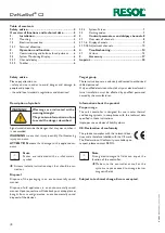
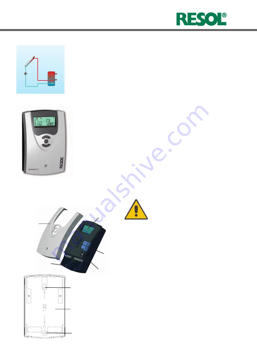
display
push button
fuse
cable conduit with
strain relief
cover
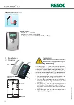
1.1 Mounting
1. Installation
130
fastening
base
Example
D e lt a S o l
®
C/2
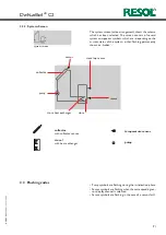
standard solar system
The unit must only be located in dry interior locations. It
is not suitable for installation in hazardous locations and
should not be placed close to any electromagnetic fields. The
controller must additionally be supplied from a double pole
switch with contact gap of at least 3 mm. Please pay atten-
tion to separate routing of sensor cables and mains cables.
1. Unscrew the cross-head screw from the cover and re-
move it along with the cover from the housing.
2. Mark the upper fastening point on the wall and drill and
fasten the enclosed wall plug and screw leaving the head
protruding.
3. Hang the housing from the upper fastening point and
mark the lower fastening point through the hole in the
terminal box (centres 130 mm). Drill and insert the lower
wall plug.
4. Hang the housing from the upper fastening point and
tighten lower fastening screw.
WARNING!
Always disconnect the controller
from power supply before open-
ing the housing!
fastening
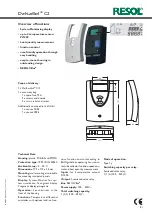
Order notes
RESOL
D e lt a S o l
®
C/2
RESOL
D e lt a S o l
®
C/2
- Full kit
incl. 2 temperature sensors Pt1000 (1 x FKP6, 1 x FRP6)


