background image

47

en

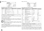
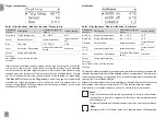
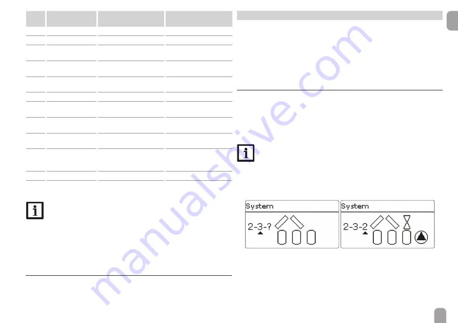
Error 
code

Display

Monitoring function

Cause 

0001

!Sensor fault

Sensor line break

Sensor line broken

0002

!Sensor fault

Sensor short circuit

Sensor line short-circuited

0011

!

D

T too high

D

T too high

Collector 50 K > than store 
to be loaded

0021

!Night circulation

Night circulation

Betw. 11 pm and 5 am col. 
temp > 40 °C

0031

!FL/RE interch.

FL/RL interchanged

Col. temp. does not rise after 
switching on

0041

!Flow rate monit.

Flow rate monitoring

No fl ow at sensor

0051

!Overpressure

Overpressure monitoring

Max. system pressure 
exceeded

0052

!Low pressure

Low pressure monitoring

System pressure below 
minimum

0061

!Data storage def.

Storing and changing adjust-
ments not possible

0071

!RTC module def.

Time-controlled functions 
(e.g. night correction) not 
possible

0081

!Store max. temp.

Maximum store temperature St. max has been exceeded

0091

Restarts

Restart counter 
(non-adjustable)

Number of restarts since 
commissioning

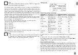
Note 
The !FL/RE interch. error can only be correctly detected and indicated, 
if the collector sensor measures the temperature directly in the fl uid at 
the collector outlet. If the collector sensor is not correctly placed, a false 
message may occur. 


Î

Place the collector sensor directly in the fl uid at the collector outlet 
or deactivate the FL/RE interch. function control.

7.7 

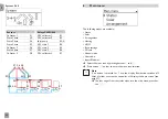
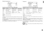
 Home  screen

In the Home screen menu, the menu which will appear if no button is pressed for 
a longer period of time can be selected.

Solar

In this menu, all adjustments for the solar part of the arrangement can be made. The 
Solar menu consists of the following submenus:
•  Basic setting
•  Optional functions
•  Function control
•  Holiday function
•  Expert
8.1 

Basic setting

In this menu, all basic settings for the solar part of the arrangement can be adjusted.
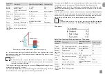
In this menu, the hydraulic system, which is the basis for the arrangement, can be 
adjusted. The setting is divided into number of collector fi elds and stores as well as 
hydraulic variant.
The number of collector fi elds and stores as well as the hydraulic variant have nor-
mally already been adjusted in the commissioning menu (see page 20). 

Note 
If the setting is changed later on, all adjustments for the solar part of the 
arrangement will be set back to their factory settings. 
If the change causes the solar system to require a relay or PWM / 0-10 V 
output that has been allocated to an arrangement or heating function 
before, the relay / PWM / 0-10 V output is removed from the non solar 
function.


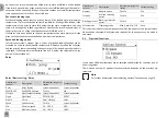
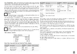
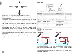
The controller supports up to 3 collector fi elds and up to 5 solar stores (with 2 or 
3 collector fi elds only up to 4 solar stores).
The following items in the Solar / Basic setting menu will adjust to the system 
selected. 

Summary of Contents for DeltaSol MX

Page 1: ...Please keep this manual safe DeltaSol MX www resol com Manual en System controller for complex solar and heating systems Manual for the specialised craftsman Installation Operation Functions and optio...

Page 2: ...ons are exclusively addressed to authorised skilled personnel Only qualified electricians are allowed to carry out electrical works Initial commissioning must be effected by authorised skilled personn...

Page 3: ...Adjusting optional functions 14 4 5 Output submenu 16 4 6 Sensor configuration 18 5 Commissioning 19 5 1 Basic systems 20 5 2 Overview of output and sensor allocation 21 6 Main menu 44 6 1 Menu struct...

Page 4: ...ating mode switches or poten tial free switches 1 frequency input 1 CS10 solar cell 2 analogue inputs for VFS RPS Grundfos Direct SensorsTM or FRH humidity sensors 2 digital inputs forVFD RPD Grundfos...

Page 5: ...at least 3 mm Please pay attention to separate routing of sensor cables and mains cables In order to mount the device to the wall carry out the following steps Unscrew the crosshead screw from the co...

Page 6: ...6 en 1 2 4 3 5 6 Chap 2 2...

Page 7: ...switch that can be accessed If the mains cable is damaged it must be replaced by a special connection cable which is available from the manufacturer or its customer service Do not use the device if i...

Page 8: ...orsTM are used connect the sensor ground common terminal block to PE Connect the analogue Grundfos Direct Sensors or FRH humidity sen sors to the Ga1 and Ga2 inputs Connect the digital Grundfos Direct...

Page 9: ...ul planning is required We recommend drawing a sketch of the system first If planning hydraulic construction and electrical connection have all been carried out successfully proceed as follows 1 Runni...

Page 10: ...ration of the controller the display is in the main menu If no button is pressed for 1 min the display illumination switches off After 4 further minutes the controller will display the home screen see...

Page 11: ...e new value The new value will be saved if it is confirmed by pressing button again active area inactive area When 2 values are locked against each other they will display a reduced adjustment range d...

Page 12: ...nu item after the list of days is Continue If Continue is selected the timer menu opens in which the time frames can be adjusted Adding a time frame In order to add a time frame proceed as follows Sel...

Page 13: ...ted for the selected day or com bination will be copied If the time frames copied are not changed the day or combination will be added to the combination from which the time frames have been copied Ch...

Page 14: ...r the timer are deleted 4 4 Adjusting optional functions In the Optional functions Add new function menus optional functions can be selected and adjusted The kind and number of optional functions offe...

Page 15: ...y saved select Delete function and confirm the security enquiry by selectingYes The function will become available under Add new function again The corresponding outputs will be available again With t...

Page 16: ...n Off 0 100 0 100 No Yes Yes irrelevant Modulating No Yes No irrelevant 0 100 If the relay option and or speed control is deactivated the adjustment in the adapter option will have no effect Adjustmen...

Page 17: ...type mixer If the temperature difference reaches or exceeds the switch on temperature differ ence the pump switches on at 100 speed for 10 s Then the speed is reduced to the minimum pump speed value I...

Page 18: ...u see page 89 Manual mode In the Manual mode adjustment channel the operating mode of the output can be selected The following options are available Off Output is switched off manual mode Min Output i...

Page 19: ...o make an adjustment press button Adjust the value by pressing buttons and then push button to confirm The next channel will appear in the display 5 5 Adjustment mode Button navigation Changing a valu...

Page 20: ...g menu First the number of collector fields and stores will have to be adjusted then the hydraulic variant Note A solar system with store loading in layers is implemented as a 2 store system store top...

Page 21: ...sors Collector 1 S1 Store base S2 Relays PWM 0 10 Solar pump R1 A System 1 2 1 Sensors Collector S1 Store 1 base S2 Store 2 base S4 Relays PWM 0 10 Solar pump R1 A 3 PV store 2 R2 System 1 1 1 5 2 Ove...

Page 22: ...Collector S1 Store 1 base S2 Store 2 base S4 Relays PWM 0 10 Solar pump store 1 R1 A Solar pump store 2 R2 B Sensors Collector S1 Store 1 base S2 Store 2 base S4 Relays PWM 0 10 Solar pump R1 A 2 PV...

Page 23: ...ector 1 S1 Store 1 base S2 Store 2 base S4 Store 3 base S5 Relays PWM 0 10 Solar pump R1 A 2 PV store 1 R2 2 PV store 2 R3 2 PV store 3 R4 Sensors Collector 1 S1 Store 1 base S2 Store 2 base S4 Store...

Page 24: ...or 1 S1 Store 1 base S2 Store 2 base S4 Store 3 base S5 Relays PWM 0 10 Solar pump R1 A 3 PV store 1 R2 3 PV store 2 R3 Sensors Collector 1 S1 Store 1 base S2 Store 2 base S4 Store 3 base S5 Store 4 b...

Page 25: ...S2 Store 2 base S4 Store 3 base S5 Store 4 base S6 Relays PWM 0 10 Solar pump R1 A 3 PV store 1 R2 3 PV store 2 R3 3 PV store 3 R4 Sensors Collector 1 S1 Store 1 base S2 Store 2 base S4 Store 3 base...

Page 26: ...Store 3 base S5 Store 4 base S6 Store 5 base S7 Relays PWM 0 10 Solar pump R1 A 2 PV store 1 R2 2 PV store 2 R3 2 PV store 3 R4 2 PV store 4 R5 2 PV store 5 R6 Sensors Collector 1 S1 Store 1 base S2...

Page 27: ...1 base S2 Store 2 base S4 Store 3 base S5 Store 4 base S6 Store 5 base S7 Relays PWM 0 10 Solar pump store 1 R1 A Solar pump store 2 R2 B Solar pump store 3 R3 C Solar pump store 4 R4 D Solar pump st...

Page 28: ...2 1 Sensors Collector 1 S1 Store base S2 Collector 2 S6 Relays PWM 0 10 2 PV collector 1 R1 2 PV collector 2 R2 Solar pump R3 A Sensors Collector 1 S1 Store 1 base S2 Store 2 base S4 Collector 2 S6 Re...

Page 29: ...tore 1 base S2 Store 2 base S4 Collector 2 S6 Relays PWM 0 10 Pump collector 1 R1 A Pump collector 2 R2 B 2 PV store 1 R3 2 PV store 2 R4 Sensors Collector 1 S1 Store 1 base S2 Store 2 base S4 Collect...

Page 30: ...2 S6 Relays PWM 0 10 2 PV collector 1 R1 2 PV collector 2 R2 Solar pump R3 A 3 PV store 2 R4 R1 R2 S2 S4 S1 S6 R4 R5 R3 A System 2 2 5 Sensors Collector 1 S1 Store 1 base S2 Store 2 base S4 Collector...

Page 31: ...Pump collector 1 R1 A Pump collector 2 R2 B 2 PV store 1 R3 2 PV store 2 R4 2 PV store 3 R5 S1 S6 S2 S4 S5 R1 A R2 B R3 C R5 R4 Sensors Collector 1 S1 Store 1 base S2 Store 2 base S4 Store 3 base S5 C...

Page 32: ...elays PWM 0 10 2 PV collector 1 R1 2 PV collector 2 R2 Solar pump R3 A 2 PV store 1 R4 2 PV store 2 R5 2 PV store 3 R6 S2 S4 S5 S1 S6 R1 A R2 B R3 R4 System 2 3 4 Sensors Collector 1 S1 Store 1 base S...

Page 33: ...llector 1 R1 2 PV collector 2 R2 Solar pump R3 A 3 PV store 1 R4 3 PV store 2 R5 S1 S2 S4 S5 S7 R4 R5 R3 R2 B S6 R1 A R6 System 2 4 1 Sensors Collector 1 S1 Store 1 base S2 Store 2 base S4 Store 3 bas...

Page 34: ...1 R1 A Pump collector 2 R2 B 3 PV store 1 R3 3 PV store 2 R4 3 PV store 3 R5 S1 S2 S4 S5 S7 R2 B R3 C R1 A R6 S6 R5 R4 D System 2 4 3 Sensors Collector 1 S1 Store 1 base S2 Store 2 base S4 Store 3 ba...

Page 35: ...llector 1 R1 2 PV collector 2 R2 Solar pump R3 A 2 PV store 1 R4 2 PV store 2 R5 2 PV store 3 R6 2 PV store 4 R7 S1 S2 S4 S5 S7 R3 A R5 R6 R4 R2 S6 R1 System 2 4 5 Sensors Collector 1 S1 Store 1 base...

Page 36: ...6 Collector 3 S8 Relays PWM 0 10 Pump collector 1 R1 A Pump collector 2 R2 B Pump collector 3 R3 C System 3 1 2 S1 S2 R1 R2 R4 S6 S8 R3 A Sensors Collector 1 S1 Store base S2 Collector 2 S6 Collector...

Page 37: ...ys PWM 0 10 Pump collector 1 R1 A Pump collector 2 R2 B 3 PV store 2 R3 Pump collector 3 R4 C R3 System 3 2 2 S1 S2 R1 A R2 B R5 C S6 S8 S4 R3 R4 Sensors Collector 1 S1 Store 1 base S2 Store 2 base S4...

Page 38: ...10 2 PV collector 1 R1 2 PV collector 2 R2 Solar pump store 1 R3 A Solar pump store 2 R4 B 2 PV collector 3 R5 System 3 2 4 S1 S2 R1 R2 R5 S6 S8 S4 R3 A R4 Sensors Collector 1 S1 Store 1 base S2 Stor...

Page 39: ...10 Pump collector 1 R1 A Pump collector 2 R2 B 2 PV store 1 R3 2 PV store 2 R4 2 PV store 3 R5 Pump collector 3 R6 C System 3 2 5 S1 S2 R1 R2 R6 S6 S8 S4 R4 R5 Sensors Collector 1 S1 Store 1 base S2...

Page 40: ...ollector 3 S8 Relays PWM 0 10 Solar pump store 1 R1 A Solar pump store 2 R2 B Solar pump store 3 R3 C 2 PV collector 1 R4 2 PV collector 2 R5 2 PV collector 3 R6 Sensors Collector 1 S1 Store 1 base S2...

Page 41: ...se S5 Collector 2 S6 Collector 3 S8 Relays PWM 0 10 Pump collector 1 R1 A Pump collector 2 R2 B 3 PV store 1 R3 3 PV store 2 R4 Pump collector 3 R5 C Sensors Collector 1 S1 Store 1 base S2 Store 2 bas...

Page 42: ...llector 1 R1 A Pump collector 2 R2 B 2 PV store 1 R3 2 PV store 2 R4 2 PV store 3 R5 2 PV store 4 R6 Pump collector 3 R7 C Sensors Collector 1 S1 Store 1 base S2 Store 2 base S4 Store 3 base S5 Collec...

Page 43: ...Relays PWM 0 10 Solar pump store 1 R1 A Solar pump store 2 R2 B Solar pump store 3 R3 C Solar pump store 4 R4 D 2 PV collector 1 R5 2 PV collector 2 R6 2 PV collector 3 R7 Sensors Collector 1 S1 Stor...

Page 44: ...3 R6 2 PV collector 3 R7 6 Main menu The following menus are available Status Solar Arrangement Heating HQM Basic settings SD card Manual mode User code Inputs Modules Select the menu area by pressin...

Page 45: ...y Mixer Zone loading Error relay Heating Shared relays Heating circuits Optional functions Screed drying Parallel relay Output Reference relay Overrun Delay Speed Basic settings Language Auto DST Date...

Page 46: ...atus information of all activated op tional functions of the arrangement 7 4 Heating In the Status Heating menu the status of the demands and heating circuits activated as well as of the selected opti...

Page 47: ...or outlet or deactivate the FL RE interch function control 7 7 Home screen In the Home screen menu the menu which will appear if no button is pressed for a longer period of time can be selected 8 Sola...

Page 48: ...of 10 K is set for the collector emer gency temperature Store 1 2 3 4 5 Solar Basic setting Store 1 2 3 4 5 Adjustment channel Description Adjustment range se lection Factory setting DTOn Switch on t...

Page 49: ...d store emergency shutdown deactivating the whole solar system as soon as one of the stores reaches 95 C 200 F Loading logic Solar Basic setting Load logic Adjustment channel Description Adjustment ra...

Page 50: ...the next store will be loaded in parallel unless it is blocked If the temperature difference falls by 2 K below the adjusted value the pump will be switched off Relay Solar Basic setting Relay Adjust...

Page 51: ...a bypass past the store Once the fluid is warm enough the store can be loaded Depending on whether the bypass is energised by a valve or by a second pump a corresponding adjustment can be made in the...

Page 52: ...ted the CS bypass will only affect the bypass For this purpose use S1 as the bypass sensor External heat exchanger Solar Opt functions Add new function Ext HX Adjustment channel Description Adjustment...

Page 53: ...e Tube collector function Solar Opt functions Add new function Tube collector Adjustment channel Description Adjustment range se lection Factory setting Start Start time frame 00 00 23 00 08 00 Stop S...

Page 54: ...new function Antifreeze Adjustment channel Description Adjustment range se lection Factory setting Antifr on Switch on temperature 40 15 C 4 C Antifr off Switch off temperature 39 16 C 6 C Collector...

Page 55: ...the store temperature exceeds the set store temperature Parallel relay Solar Opt functions Add new function Parallel relay Adjustment channel Description Adjustment range se lection Factory setting Ou...

Page 56: ...ency shutdown temperature or until the switch off temperature difference is reached Collector cooling type If the collector maximum temperature is exceeded the stores will be loaded above their respec...

Page 57: ...ng time has ended The parameter Initialis is used for adjusting the period during which the switch on condition must be permanently fulfilled before the filling process starts The Booster option is us...

Page 58: ...ted instead The twin pump function no longer takes place until the error message has been acknowledged When the error message is acknowledged the controller runs a test during which it energises the c...

Page 59: ...Store Store selection system dependent 1 Time Delay time 1 300s 30 s Funct Activation Deactivation Activated Deactivated Switch Activated Sensor Switch input selection Save func tion Delete function...

Page 60: ...will be shut down as well in case of a fault condition When the pressure reaches or falls below the adjustable switch off value Off the system is switched on again Note For the Overpressure monitorin...

Page 61: ...maximum store temperature by at least 5 K The monitoring becomes active again as soon as the store temperature falls below the adjusted maximum store temperature In the Store channel the store or sto...

Page 62: ...tors from overheating The store heat dump function is inde pendent of the solar system and can be activated with the parameter Heat dump The function uses the adjustable switch on and switch off tempe...

Page 63: ...me 1 30 min 1 min Funct Activation Deactivation Activated Deactivated Switch Activated Sensor Switch input selection Save func tion Delete function Save or delete function This function can be used fo...

Page 64: ...ription Adjustment range selection Factory setting Save func tion Delete function Save or delete function This function can be used for loading a store zone between 2 sensors For monitor ing the switc...

Page 65: ...ce the temperature difference between the allocated sensors has not fallen below the switch off temperature difference the temperature at the heat source sensor has exceeded the minimum temper ature t...

Page 66: ...mperature at the store sensor is below the maximum temperature one of the adjusted time frames is active if the Timer option is selected When the set temperature difference is exceeded pump speed cont...

Page 67: ...ory setting Output Output selection system dependent system depend ent Thermostat a Thermostat function a Yes No No Th a on Switch on temperature ther mostat a 40 250 C 40 C Th a off Switch off temper...

Page 68: ...on temperature DTOn is reached The switching condition for the DT function is no longer considered fulfilled when the adjusted switch off temperature DTOff is reached The DT function is equipped with...

Page 69: ...c tion Delete function Save or delete function This function can be used for operating an output depending on the measured irradiation value The allocated output will be switched on if the adjusted ir...

Page 70: ...mixing temperature If the store temperature falls below the heating circuit return temperature by the switch off temperature difference the mixer will close The runtime defines the time needed for the...

Page 71: ...demand the same heat source Note Activate and adjust the shared relays first They will then be available in the heating circuits and optional functions Heating Shared rel A d j u s t m e n t channel D...

Page 72: ...otential free relay R14 can be allocated to the shared relay Dem 1 for exam ple R14 will then become available for potential free boiler demand in the heating circuits and e g the DHW heating function...

Page 73: ...he adjusted duration has elapsed the allocated output switches on The Overrun option is used for switching off the loading pump with a delay to a demand If the temperature falls below the adjusted rem...

Page 74: ...outdoor temperature sensor is defective an error message will be indicated For the duration of this condition the maximum flow temperature 5K is assumed as the set flow temperature in the Curve and L...

Page 75: ...TStart In order to calculate the deviation of the room temperature from the adjusted set value at least one sensor type room thermostat is required see page 76 The adjustments can be made with the Roo...

Page 76: ...ch of the room control unit is used for adjusting the op erating mode of the controller If a room control unit is used the operating mode can be adjusted by means of the room control unit only The sta...

Page 77: ...set flow temperature is compared to 2 store reference sensors The switching conditions have to be fulfilled at both reference sensors On Off In this mode the backup heating is activated when the heati...

Page 78: ...weeper mode is automatically deactivated If during the countdown button is again pressed for more than 5 s the chimney sweeper mode will stop Antifreeze function The antifreeze function of the heating...

Page 79: ...esults from the dew point plus the adjustable correction value The emergency shutdown option is used for switching off the cooling if the adjustable relative humidity is exceeded The re energise hyste...

Page 80: ...ection for night operation 20 30K 5K Timer Timer function correction mode Yes No No Mode Correction mode Day Night Day Off Day Night Timer Timer function submenu Summer oper Summer operation option Ye...

Page 81: ...temperature 15 45 C 20 C TFlow 1 Lower set flow temperature 5 25 C 20 C TOutdoor 2 Upper outdoor temperature 15 45 C 40 C TFlow 2 Upper set flow temperature 5 25 C 10 C TFlowmin Minimum flow temperatu...

Page 82: ...ncellation interval 1 0 48 0 h 2 0 h Start time Starting delay option Yes No No Start time Starting time 00 00 23 30 20 00 Hyst off Switch off hysteresis 2 20K 5K Hyst on Switch on hysteresis 1 19K 2K...

Page 83: ...re 1 95 C 45 C Timer Timer function Yes No No Man heating Manual heating option Yes No No Sensor Switch input selection system dependent system depend ent Adjustment channel Description Adjustment ran...

Page 84: ...e sensor IMP1 IMP3 Ga1 Ga2 Gd1 Gd2 FR1 TMax DHW DHW maximum temperature 20 90 C 60 C Start speed Starting speed DHW preheating 20 100 50 Increment Increment speed adaptation 1 100 10 Hysteresis Hyster...

Page 85: ...sor is monitored The allocated output switch es on when the temperature falls below the adjusted switch on temperature If the temperature exceeds the switch off temperature the output switches off Tim...

Page 86: ...ge to the screed drying status menu The cur rent Phase will be indicated on the display and the Remaining time will be indi cated as a countdown dd hh During this process the directional pad flashes g...

Page 87: ...ustments When the screed drying function has been successfully completed the correspond ing heating circuits will change to their operating modes selected Screed drying will automatically be deactivat...

Page 88: ...tity balancing is in effect whenever the allocated relay is active In the adjustment channel Fluid type the heat transfer fluid must be selected If either propylene glycol or ethylene glycol is select...

Page 89: ...card Safely remove card Save adjustments Save adjustments Load adjustments Load adjustments Logging int Logging interval 00 01 20 00 mm ss 01 00 Logging type Logging type Cyclic Linear Linear The con...

Page 90: ...D card Loading controller adjustments To load controller adjustments from an SD card select the menu item Load adjustments The file selection window will appear Select the desired SET file While the a...

Page 91: ...acknowledged by the controller are available To register a module select the corresponding menu item by pressing button The checkbox indicates the selection If a module is registered all its sensor in...

Page 92: ...are used connect the sensor ground common terminal block to PE see page 7 Inputs Modules Inputs Adjustment channel Description Adjustment range selection Factory setting S1 S12 Sensor input selection...

Page 93: ...1078 1922 85 185 664 1328 3071 25 77 549 1097 2000 90 194 634 1347 3172 30 86 559 1117 2079 95 203 683 1366 3275 35 95 568 1136 2159 100 212 693 1385 3380 40 104 578 1155 2242 105 221 702 1404 3484 4...

Page 94: ...rence between store and collector increases enormously during operation the collector circuit cannot dissipate the heat Collector circuit pump defective no yes Heat exchanger calcified yes Check repla...

Page 95: ...y illuminated If not press button Display illuminated again Does the pump start up in manual operation The solar circuit pump does not work although the collector is considerably warmer than the store...

Page 96: ...S VFD RPD Grundfos Direct SensorsTM Analogue digital sensors in different versions V40 Flowmeter TheV40 is a measuring instrument for detecting the flow of water or water glycol mixtures AM1 Alarm mod...

Page 97: ...ter It enables easy access to the controller via the local network of the owner TheVBus Modbus interface adapter is designed for the connection of the controller to a local network for communication v...

Page 98: ...Commissioning menu 19 Controller adjustments loading of 90 Cooling mode 56 Cooling system 78 Correction modes 77 Countdown 78 CS bypass 52 D Data logging 90 Day correction 74 Day Night operation 75 D...

Page 99: ...g circuit 76 Remote control 74 76 Return mixing function 69 Return preheating 66 Room control heating circuit 75 Room control unit 76 S Screed drying 86 Sensor offset 92 Set flow temperature 74 Set st...

Page 100: ...the completeness of the drawings and texts of this manual they only represent some ex amples They can only be used at your own risk No liability is assumed for incorrect incomplete or false informati...

Reviews: