8
en
The V40 flowmeters can be connected to the terminals S13 / IMP1 to S15 / IMP3
and GND (either polarity).
Connect the irradiation sensor CS10 to the terminals CS10 and GND with cor-
rect polarity. To do so, connect the cable marked GND to the GND common ter-
minal block, the cable marked CS to the terminal marked CS10.
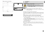
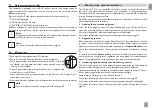
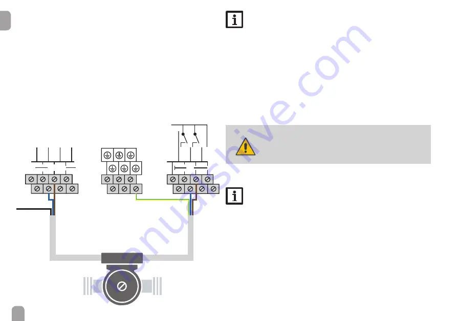
The terminals marked PWM / 0-10 V are control outputs for high-efficiency pumps
(for connection see illustration).
Electrical connection of a high-efficiency pump (HE pump)
Speed control of a HE pump is possible via a PWM signal / 0-10 V control. The pump
has to be connected to the relay (power supply) as well as to one of the PWM out-
puts of the controller. In the Output adjustment channel one of the PWM control
types as well as a relay have to be selected (see page 16).
R2
R1
GND
PWM
N
X
Note
When Grundfos Direct Sensors
TM
are used, connect the sensor ground
common terminal block to PE.
Connect the analogue Grundfos Direct Sensors™ or FRH humidity sen-
sors to the Ga1 and Ga2 inputs.
Connect the digital Grundfos Direct Sensors™ or FRHd humidity sensors
to the Gd1 and Gd2 inputs.
Connect the flow rate sensor with frequency signal to the FR1 input.
The controller is supplied with power via a mains cable. The power supply of the
device must be 100 … 240 V~ (50 … 60 Hz).
Connect the mains cable to the following terminals:
Neutral conductor N
Conductor L
Protective earth conductor
⏚
(common terminal block)
WARNING!
Danger of electric shock!
L' is a fused contact permanently carrying voltage.
Î
Always disconnect the device from power supply
before opening the housing!
Conductor L' (L' is not connected with the mains cable. L' is a fused contact
permanently carrying voltage.)
Note
For more details about the commissioning procedure see page 9.
Signal cable
PWM
Signal input
Pump
Power supply
Pump
Power
supply
230 V~
blue
blue
brown
brown
black
(not used)
yellow/green
Summary of Contents for DeltaSol MX
Page 6: ...6 en 1 2 4 3 5 6 Chap 2 2...


