background image

FlowCon B

© RESOL 08239 Flo

wcon_B.monen.ind

d

|


4


16

1

2

8

14

10

9

13

7

3

15

4

6

11

5

1.  Installation

12

1.1 Wall mounting

1. 

Determine where to mount the pump station; consider 
the space for the (optional) expansion vessel!

2. 

Take the complete station out of the packing.

3. 

Remove the front half of the insulation by pulling it. The 
thermometers loosen from the ball valves. 


Do not unsrew the pump station from the back 
part of the insulation!

4. 

Mark the fastening holes (centres 70 mm) and drill holes 
(diameter 8 mm); insert the enclosed dowels (S 8).

5. 

Fasten  the  complete  pump  station  with  the  wall 
mounting bracket to the wall (depending on the pump 
version, upper or lower holes in the insulated casing) 

and tighten the screws. For this purpose, use a positive 
cross-recessed screwdriver!

6. 

Connect  the  connection  line  between  the  pump 
station and the store and the collectors repectively.  
 

Optionally, 

compression ring connections can be used 

for mounting copper pipes.

 In order to connect the 

pipes with the compression ring connections, 
pay attention to the following instructions!

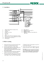
Wall mounting bracket of the pump station 


Insulation - rear 


Controller 


Insulation - front cover 


Flowmeter 


Drain valve 


pump  


ball valve in flow IT-IT, with integrated thermometer 

ball valve in return IT-IT, with integrated thermometer

10 

Safety head-piece, with fill valve

11 

Pressure gauge

12 

Safety valve 6 bar

13 

Optional:

 expansion vessel set

14 

Optional:

 AirStopp 

15 

Optional:

 Compression ring connection for  

 copper pipe

Summary of Contents for FlowCon B

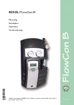
Page 1: ... resol de Manual B RESOL FlowCon B Mounting Installation Operation Commissioning Thank you for buying this RESOL product Please read this manual carefully to get the best performance from this unit 48001070 48001070 ...

Page 2: ...nel Only qualified electricians should carry out electrical works Initial installation must be effected by qualified personnel named by the manufacturer Declaration of conformity We RESOL Elektronische Regelungen GmbH D 45527 Hattingen declare under our sole responsibility that our product FlowCon B complies with the following standards EN 55 014 1 EN 60 730 1 According to the regulations of the a...

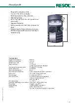
Page 3: ... 315 mm Distance axis wall 63 mm Pipe connections IT with cutting ring connections optional Connection for expansion vessel ET pipe 3 4 flat sealing Outlet safety valve ET pipe 3 4 Max admissible pressure 8 bar Max admissible temperature 120 C continuous and 160 C intermittent Safety valve 1 2 x 3 4 3 bar 6 bar 10 bar Pressure gauge 0 6 bar up to 130 C Non return valve 2 x 200 mm water column open...

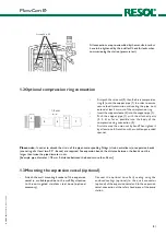
Page 4: ...r or lower holes in the insulated casing and tighten the screws For this purpose use a positive cross recessed screwdriver 6 Connect the connection line between the pump station and the store and the collectors repectively Optionally compression ring connections can be used for mounting copper pipes In order to connect the pipes with the compression ring connections pay attention to the following ...

Page 5: ...ll rotation with a suitable open ended spanner Please note In order to absorb the strain of the pipes corresponding fittings strain neutralizers or expansion bends consisting of at least two 90 bends are required For expansion bends the distance between the bends must be larger than twice the pipe diameter in cm Example pipe diameter 18 mm Þ distance between the bends more than 36 cm 1 2Optional c...

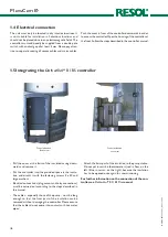
Page 6: ...of the insulated casing down wards and remove it Put the controller into the provided space in the insula tion and attacht it with the fastening screws 3 x 30 and large washers Electrical connections plug sensor and relay connections must be carried out according to the steps described in the manual The cables especially those of the pump must be long enough so that the front part of the insulatio...

Page 7: ...approx 6 bar The system pressure is indicated at the pressure gauge Close the fill valve and switch off the pump of the flushing and filling station open the adjustment screw at the flowmeter vertical position Bleed the system above the collector until the dis charged fluid is free of bubbles Increase the pressure to approx 6 bar and check the system for leaks In the case of a significant decrease...

Page 8: ... of the valve must not be influenced or disabled by barriers The strainer or other restriction devices must not be mounted between collector field and safety valve The diameter of the discharge pipe must correspond to the diameter of the valve outlet the maximum length must not exceed 2 m more than 2 bends are inadmiss able When these values are exceeded 2 bends 2 m pipe length you have to install...

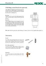
Page 9: ...ekly or monthly depending on the volume of discharged air Bleed the solar thermal system half yearly with the manual bleed valve to achieve optimal efficiency Plese note Check the system pressure after bleeding and if necessary increase it to the specified operating pressure 3 Accessory Overvoltage protection In order to avoid overvoltage damage at collector sensors e g caused by local lightning s...

Page 10: ...FlowCon B RESOL 08239 Flowcon_B monen indd 10 Notes ...

Page 11: ...FlowCon B RESOL 08239 Flowcon_B monen indd 11 Notes ...

Page 12: ...e do not offer a guarantee for the completeness of the drawings and texts of this manual they only represent some examples They can only be used at your own risk No liability is assumed for incorrect incomplete or false information and or the resulting damages Please note The design and the specifications are to be changed without prior notice The illustrations may differ from the original product...

Reviews: