FlowCon B
© RESOL 08239 Flo
wcon_B.monen.ind
d
5
|
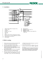
All connections are pre-assembled by the manufacturer but
have to be tightened by the installer. Check for leaks when
commissioning the station (pressure test).
Screws S6 x 60
-
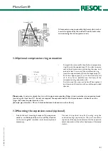
First push the union nut (2), then the brass compression
ring (3) onto the copper pipe (1). In order to ensure
secure load transmission and sealing, the pipe must
extend at leat 3 mm out of the compression ring.
-
Insert the support sleeve (4) into the copper pipe (1).
-
Push the copper pipe (1) with the attached parts
(2; 3; 4) as far as possible into the body of the
compression ring connection (2).
-
First screw on the union nut by hand. Then tighten it
by at least one full rotation with a suitable open-ended
spanner.
Please note:
In order to absorb the strain of the pipes, corresponding fittings (strain neutralizers) or expansion bends
(consisting of at least two 90° - bends) are required. For expansion bends, the distance between the bends must be
larger than twice the pipe diameter in cm.
[Example: pipe diameter = 18 mm Þ distance between the bends more than 36 cm].
1.2 Optional compression ring connection
1.3 Mounting the expansion vessel (optional)
-
Attach the wall mounting bracket of the expansion
vessel in a suitable position to the wall. Pay attention
to the corrugated stainless steel hose (optional
accessory).
-
Connect the optional hose flatly sealing using the
enclosed sealings (optional) to the quick connector
(optional) of the expansion vessel and to the expansion
vessel connection at the safety head piece of the pump
station.
5
3
2
1
> 3 mm
4

