background image

en

6

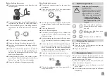
Flow rate measurement

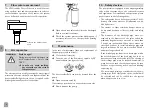
The VFS Grundfos Direct Sensor

TM

 is used for meas-

uring the flow rate and the temperature. In order to 
ensure faultless operation of the sensor, the system 
has to be flushed and must be free of dirt particles.

orifice in the measurement  
head

Air separator

WARNING!

Scald danger! 
During venting, the air discharged can 
reach temperatures of more than 
100 °C. 


Î

In order to avoid scalding, 
pay attention to the system 
temperatures!

The air separator is used for venting the water / glycol 
mixture in the solar circuit. The air separated from the 
heat transfer fluid gathers in the air scoop and can be 
discharged manually at the air vent valve.


Î

Open the air vent valve and collect the discharged 
fluid in a suitable container. 


Î

Check the system pressure after bleeding and, if 
necessary, increase it to the specified operating 
pressure.

Maintenance

In the case of maintenance (such as a replacement of 
the pump) proceed as follows:


Î

Close the ball valve (4).


Î

Turn the slot of the flowmeter spindle by 90° 
anti-clockwise (see figure below).

The heat transfer fluid can now be drained from the 
pump.


Î

Open the drain valve (3). 

If necessary, open the union nut at the pressure side.


Î

Now dismount the pump.

10  Safety devices

The pump station is equipped with a diaphragm safety 
valve which corresponds to the relevant directives 
and regulations. For installation and operation, please 
pay attention to the following advice:
•  The safety valve has to be easily accessible. The ef-

ficiency of the valve must not be influenced or disa-
bled by barriers!

•  The strainer or other restriction devices must not 

be mounted between collector (-field) and safety 
valve!

•  The diameter of the discharge pipe must cor-

respond to the diameter of the valve outlet; the 
maximum length must not exceed 2 m; more than 
2 bends are inadmissible. When these values are 
exceeded, you have to install a discharge pipe with 
larger dimensions. Do not use more than 3 bends 
and pipes longer than 4 m!

•  If the discharge pipe leads into a drain pipe with a 

funnel, the diameter of the drain pipe has to be at 
least twice as large as the valve inlet. The opening of 
the discharge pipe must be inclined downwards. It 
must be routed such that the opening can be seen 
but does not present any risk to a person standing 
or passing by.

•  We recommend placing a container below the dis-

charge pipe. If the safety valve opens, the fluid will 
be collected and can be refilled into the system 
when the pressure is too low.

Summary of Contents for FlowSol B HE WMZ

Page 1: ...his RESOL product Please read this manual carefully to get the best performance from this unit Please keep this manual carefully www resol com Manual en Installation Operation Commissioning Manual for the specialised craftsman FlowSol B HE WMZ ...

Page 2: ...qualified per sonnel named by the manufacturer Contents 1 Overview 3 2 Mounting the station 4 3 Flushing and filling the solar system 4 4 Ball valve positions 5 5 Draining the system 5 6 Non return valves 5 7 Flow rate measurement 6 8 Air separator 6 9 Maintenance 6 10 Safety devices 6 11 Accessories 7 12 Information about the pump 7 13 Lists of spare parts 7 Description of symbols WARNING Warning...

Page 3: ...PWM2 12 power consumption of the pump 25W Safety valve 6 bar Pressure gauge 0 10bar Grundfos Direct Sensor VFS 1 12 VFS 2 40 Non return valves Opening pressure 20mbar openable Connection to diaphragm type expansion vessel ET flat sealing Outlet safety valve IT Connections to the solar pipes IT atVFS ET Maximum temperature flow return 120 C 95 C Maximum pressure 6 bar Medium Water with max 50 glyco...

Page 4: ...ween pump station and store and collector respectively Note All connections are already tightened such that they usually do not have to be tightened again However during commissioning of the system all connections have to be checked for leaks pressure test 3 Flushing and filling the solar system WARNING Scald danger Pressure surge damage If the medium enters strongly heat ed empty collectors press...

Page 5: ...e necessary Î Î Slowly discharge the heat transfer fluid by means of the drain valve 3 until the operating pressure is set Î Î Remove the hoses of the filling and flushing sta tion and screw the caps onto the fill and drain valves Manually start the solar thermal pump at maximum speed see controller manual and let the fluid circulate for at least 15 minutes Î Î Bleed the solar thermal system sever...

Page 6: ...n valve 3 If necessary open the union nut at the pressure side Î Î Now dismount the pump 10 Safety devices The pump station is equipped with a diaphragm safety valve which corresponds to the relevant directives and regulations For installation and operation please pay attention to the following advice The safety valve has to be easily accessible The ef ficiency of the valve must not be influenced ...

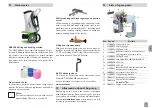
Page 7: ...ing and flushing station The SBS 2000 has been especially designed for pro fessionally filling and flushing solar thermal and heat ing systems Its many thought out details facilitate transport operation and cleaning the attractive de sign makes it the ideal companion for a professional performance Heat transfer fluids In our product portfolio you will find a range of heat transfer fluids for diffe...

Page 8: ...or the completeness of the drawings and texts of this manual they only represent some examples They can only be used at your own risk No liability is assumed for incorrect incomplete or false information and or the resulting damages Note The design and the specifications can be changed without notice The illustrations may differ from the original product Imprint This mounting and operation manual ...

Reviews: