background image

© RESOL 11294 flo

wsol_d_d_he

.monen.ind

d

FlowSol D / D HE

| 2

Table of contents

Safety instructions .................................................... 3
1.  Pump station with integrated controller ......... 3
2.  Mounting the station .......................................... 5
3.  Commissioning ................................................... 6

3.1  Flushing and filling the solar thermal system .......6
3.2  Emptying the solar thermal system ........................8

4.  AirStopp .............................................................. 8
5.  Digital sensors ..................................................... 9
6.  Connection .......................................................... 9
7.  Accessories for the station ................................ 9
8.  Integrated controller 

DeltaSol

®


D / D HE ... 10

9.  Installation ......................................................... 11
10. Sensor and relay allocation ............................. 11

Description of symbols

Signal words describe the danger that may occur, when it 
is not avoided.
WARNING means that injury, possibly life-threatening 
injury, can occur.
ATTENTION means that damage to the appliance can 
occur.

Information about the product

Proper usage
The solar controller is designed for use in standard solar 
thermal systems and heating systems in compliance with the 
technical data specified in this manual.
Improper use excludes all liability claims.

CE-Declaration of conformity
The product complies with the relevant direc-
tives and is therefore labelled with the CE mark. 
The Declaration of Conformity is available upon 
request, please contact RESOL.

Note

Notes  are  indicated  with  an  information 
symbol.

Disposal

Dispose of the packaging in an environmentally sound 
manner.
Dispose of old appliances in an environmentally sound 
manner. Upon request we will take back your old  appliances 
bought from us and guarantee an environmentally sound 
disposal of the devices.


Î

Arrows indicate instruction steps that should be carried 
out.

WARNING!

Warnings are indicated with a 
warning triangle!
They contain information on how 
to avoid the danger described.

Safety advice
Please pay attention to:
- safety advice in order to avoid danger and damage to  
  people and property.
- the valid local standards, regulations and directives!

Target group
These instructions are exclusively addressed to authorised 
skilled personnel.
Only qualified electricians should carry out electrical works.
Initial installation must be effected by qualified personnel 
named by the manufacturer.

Note
Strong electromagnetic fields can impair the 
function of the controller.


Î

Make sure the controller as well as the 
system are not exposed to strong electro-
magnetic fields.

11. Operation and function ................................... 11

11.1  Adjustment keys ...................................................... 11
11.2  Menu structure ........................................................ 12
11.3  Operation  ................................................................ 14
11.4  User code ................................................................. 14

12. Display mode .................................................... 15

12.1  Status, measurement values and balance values 15
12.2  Balance values .......................................................... 16

13. Functions and options ...................................... 16
14. Messages ............................................................ 19
15. Electrical connection........................................ 21
Imprint .................................................................... 24

Summary of Contents for FlowSol D

Page 1: ...RESOL FlowSol D D HE Installation Operation Commissioning Thank you for buying this RESOL product Please read this manual carefully to get the best performance from this unit FlowSol D D HE www resol...

Page 2: ...ted with an information symbol Disposal Dispose of the packaging in an environmentally sound manner Dispose of old appliances in an environmentally sound manner Upon request we will take back your old...

Page 3: ...ressure and flow rate AirStopp for manual bleeding of the solar thermal system Manometer for displaying the system pressure Safety valve to prevent inadmissible overpressure High efficiency pump on Fl...

Page 4: ...Outlet safety valve 3 4 IT Equipment Safety valve 6 bar Manometer 0 6 bar Non return valves Opening pressure 200 mmWS openable Material Fittings brass Seals EPDM Insulation EPP l 0 041 W m K Technica...

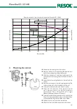
Page 5: ...cket against the wall and mark the fastening holes drill holes and insert dowels Fasten the wall mounting bracket to the wall with the screws Push the station against the wall mounting bracket The sta...

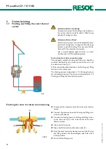
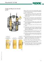
Page 6: ...ct the pressure hose of a flushing and filling stati on to the fill valve 3 Connect the flushing hose of a flushing and filling station to the drain valve 5 at the lowest point of the solar thermal sy...

Page 7: ...e the system pressure to approx 5 bar The system pressure can be read from the manometer Close the fill valve 3 and switch off the pump of the flushing and filling station as well as the solar pump Ch...

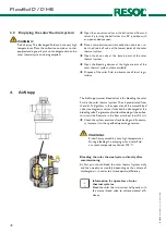
Page 8: ...s The AirStopp manual bleed valve is for bleeding the solar fluid in the solar thermal system The air precipitated from the solar fluid gathers in the upper area of the manual bleed valve see diagram...

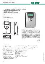
Page 9: ...rom power supply before opening the housing The controller is already integrated in the station and ready to plug in In the case of maintenance or service work the controller is to be taken out from t...

Page 10: ...er for the solar pump tube collector function and heat quantity measurement Inputs for 3 temperature sensors Pt1000 2 digital sensors Outputs 1 semiconductor relay Bus RESOLVBus Power supply 100 240V...

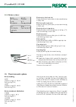
Page 11: ...ow the display Button 1 is used for scrolling forward through the menu or to increase the adjustment values Button 2 is similarly used for scrolling backwards and reducing values Button 3 is used for...

Page 12: ...DToff switch off difference 0 0 24 0 K 3 0 K DTset set difference 2 50 K 10 K Relay mode Off Auto Min Max Auto expert DTstmax maximum store hysteresis 1 0 10 0 K 2 0 K Tstsec store emergency shutdown...

Page 13: ...1 60 min 30 min runtime 5 1200 s 30 s start 00 00 23 59 07 00 stop 00 00 23 59 19 00 antifr type Tyfo LS Ethylene Propylene Water Tyfo LS antifreeze ratio 20 70 40 DT too high Yes No No Non ret valve...

Page 14: ...e function Briefly press button 3 to confirm the selection Press button 3 again in order to store the selection An activated function is indicated by means of a marked checkbox The corresponding adjus...

Page 15: ...the balance value display the following temperature courses in C are shown one after the other over time collector today store today collector yesterday store yesterday Measurement values Balance valu...

Page 16: ...balance values can be reset in the balance and adjust ment menu Keep button 3 pressed for 2 seconds This changes the display to show the balance values and adjustment values Select the balance value w...

Page 17: ...ax can be 10 K lower than the collector emergency shutdown tem perature and 10 K higher than the maximum store tempe rature blocking Collector emergency shutdown Tcolsec adjustment range 20 180 C fact...

Page 18: ...ory setting 30 min runtime adjustment range 5 500 s factory setting 30 s start adjustment range 00 00 23 59 factory setting 07 00 stop adjustment range 00 00 23 59 factory setting 19 00 This function...

Page 19: ...Power Error S2 defect P V broken 78 6 C 92 C 34 5 C 80 broken The defective sensor is indicated If the cable of a temperature sensor is broken broken is displayed if the cable of a temperature sensor...

Page 20: ...pressure and flow rate will no longer be carried out Error message flow rate flow rate selection Yes No factory setting No If no flow rate is measured within 10 seconds after the solar ciruit has bee...

Page 21: ...r S2 sensor 2 sensor store base S3 sensor 3 sensor store top The mains connection is at the terminals 16 neutral conductor N 17 conductor L 11 ground terminal Important note The mains connection must...

Page 22: ...RESOL 11294 flowsol_d_d_he monen indd FlowSol D D HE 22 Note...

Page 23: ...RESOL 11294 flowsol_d_d_he monen indd FlowSol D D HE 23 Note...

Page 24: ...Regelungen GmbH This especially applies for copies translations micro films and the storage into electronic systems Editor RESOL Elektronische Regelungen GmbH Important notice We took a lot of care w...

Reviews: