© RESOL 11294 flo
wsol_d_d_he
.monen.ind
d
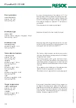
FlowSol D / D HE
11 |
9. Installation
PE
Pump (R1)
Mains
11
12
13
14
15
16
17
N
L
N
L
collector circuit
pump
mains
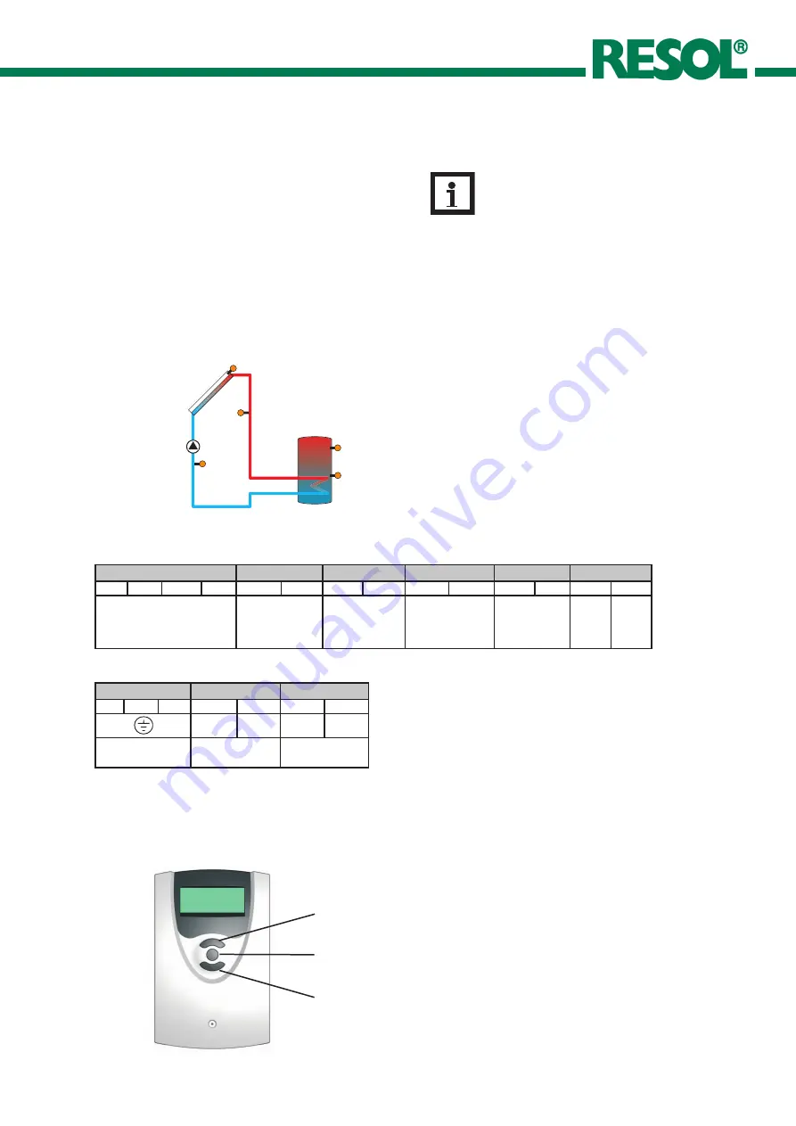
10. Sensor and relay allocation
Sensor allocation
Relay allocation
1
2
3
backwards
SET
(selection-/
adjustment mode)
11. Operation and function
11.1 Adjustment keys
When the hydraulic system is filled and ready for operation,
connect the controller to the mains.
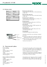
The controller is operated by means of the 3 push buttons
below the display.
•
Button 1 is used for scrolling forward through the menu
or to increase the adjustment values.
•
Button 2 is similarly used for scrolling backwards and
reducing values.
•
Button 3 is used for selection of the menu lines and for
confirmation.
forwards
Digital Sensor
S1
R1
S2
S3
Digital Sensor
Digital Sensor
Tcol (S1)
Tstb (S2)
Tstt (S3)
VBus
PWM
A
B
C
D
1
2
3
4
5
6
7
8
9
10
digital sensors
sensor
collector
sensor store,
bottom
ensor store,
top
blue brown
A = brown
B = green
C = white
D = yellow
Note:
The controller is already integrated in the sta-
tion and ready to plug in. In the case of mainte-
nance work and repair, pay attention to chapter
15 ‚Electrical connection‘!

