background image


30 


WARRANTY


MANUFACTURER’S LIMITED WARRANTY 
Paradigm Health & Wellness warrants to the original purchaser that this product is free from 

defects  in  material  and  workmanship  when  used  for  the  purpose  intended,  under  the 

conditions that it has been 

installed and operated in accordance with Paradigm’s Owner’s 

Manual. Paradigm’s obligation under this warranty applies to the following: 


COMPONENT                      LENGTH OF WARRANTY   

Structural Frame 

10 years   

Motor     

3 years   

All Other Components 

1 year 

(computer display, electronics, upholstery, foam, ball bearings, pulleys, belts, cables, wires, 

shocks,  covers,  tension,  internal  mechanism,  wheels,  pedals,  knobs,  accessories  and 

hardware) 

Exclusions from Warranty Coverage: 

Paradigm does not warrant against and is not responsible for, and no implied warranty shall be deemed to cover, any 
product failure, product malfunction, or damages attributable to: 
1. Improper installation and/or failure to abid

e by Paradigm’s installation guidelines; 

2. Use of this product beyond normal home use, or in an application for which it was not designed; 
3. Cosmetic items such as scratches, dents or discolorations; 
4. Damage caused by normal wear and tear, vandalism, accidental or by animals; 
5. Any act of Nature (such as fire, flooding, snow, ice, hurricane, earthquake, lightning or other natural disaster), 

environmental condition (such as air pollution, mold, mildew, etc.), or staining from foreign substances (such as dirt, 
grease, oil, etc.); 

6. Normal weathering due to exposure to sunlight, weather and atmosphere which can cause colored surfaces to, 

among other things, flake, chalk, accumulate dirt or stains. 

7. Improper operation, alteration, handling, storage, abuse or neglect of the products. 

Paradigm, using its sole discretion, will either repair or replace free of charge any part(s) proven to 

be defective under normal home use. Any repair or replacement shall provide no new warranty 

coverage, but shall retain onl

y the remaining portion of the original product’s warranty. This 

warranty is offered only to the original purchaser and is not transferable. Proof of original purchase 

is required. 

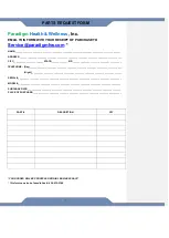
Ordering Replacement Parts


Replacement parts can be ordered by emailing our customer service department: 

Service@paradigmhw.com 

Open Monday thru Friday 8:00 AM - 5:00 PM (PST). 

When ordering replacement parts please have the following information ready: 

1. Owner’s Manual 

2. Model Number 

3. Description of Parts 

4. Part Number 

5. Date of Purchase 


Summary of Contents for R1 Sled Treadmill

Page 1: ...6040 2 100219 R1 Sled Treadmill...

Page 2: ...TO THE STORE STOP Contact customer service if you have any questions regarding assembly or proper operation of the machine Email us at Service paradigmhw com Or call us at 1 844 641 7923 Hours 8 00 am...

Page 3: ...LABEL PLACEMENT 3 IMPORTANT SAFETY GUIDELINES 4 OVERVIEW DRAWING 6 PARTS LIST 7 HARDWARE TOOL LIST 9 ASSEMBLY 10 CONSOLE 22 ADJUSTMENTS 25 TRANSPORTING STORAGE 26 MAINTENANCE TROUBLESHOOTING 27 WARRA...

Page 4: ...the best method to receive a response during peak business hours Website www paradigmhw com Toll Free 1 844 641 7923 8 00 AM 5 00 PM Pacific Standard Time Monday thru Friday Response time may vary vi...

Page 5: ...3 LABEL PLACEMENT...

Page 6: ...of lint hair and the like Do not use the treadmill outdoors Keep children and pets away from the equipment while in use This machine is designed for adults only This appliance is not intended for use...

Page 7: ...al capabilities or lack of experience and knowledge unless they have been given supervision or instruction concerning use of the appliance by a person responsible for their safety Children should be s...

Page 8: ...ury to Persons To Avoid Injury use extreme caution when stepping onto or off of moving the running belt Read Instruction Manual Before Using Formatted Font 15 pt Formatted Font 15 pt Formatted Normal...

Page 9: ...ment We assume no responsibility for personal injury or property damage sustained by or through the use of this product Do not operate this exercise equipment without properly fitted guards as the mov...

Page 10: ...8 OVERVIEW DRAWING...
Page 11: ...nting 1 55 Screw M5 12L 6 18 Stainless Screw M5 8L 8 56 Flat Washer M8 16 2 0 18 19 Flywheel 1 57 Front Lower Cable 1 20 Blade 1 58 Rear Lower Cable 1 21 Screw M10 25L 1 59 Guiding Wheel L 1 22 Belt P...

Page 12: ...rRear Rail Plug Right 1 83 Motor cover up 1 96 Step On Cover 2 84 Screw M5 16L 4 97 Upright Cap L 1 85 Screw M4 16L 14 98 Upright Cap R 1 86 Motor cover Left 1 99 Flat Washer M4 12 1 0 4 87 Magnet Bra...

Page 13: ...nch 1 PC 6mm Allen Wrench 1 PC 5mm Allen Wrench 1 PC Double Wrench 1 PC 50 Screw M5x10L 2PCS 51 Screw M6x12L 4PCS 55 Screw M5x12L 6PCS 52 Screw M10x25L 8PCS 54 Screw M6x12L 4PCS 53 Screw M8x16L 44PCS...

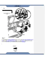
Page 14: ...ide it onto the Main Frame 1 Tighten the Right Upright Post 66 with four Screws 53 and four Flat Washers 56 using the 6mm Allen Wrench provided 50 Phillips Screw 2 PCS Hardware Screwdriver 1 PC Tool 6...

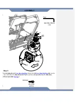
Page 15: ...r Cable 67 See Fig B 2b Installing the Left Upright Post SLOWLY slide the Left Upright Post 65 onto the Main Frame 1 Tighten the Left Upright Post 65 with four Screws 53 and four Flat Washers 56 using...

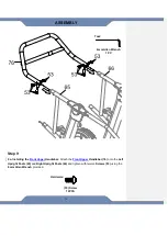
Page 16: ...me 1 Tighten the Right Right Rear HandlebarSide Handlebar 74 to the Right Upright Post 66 with four six Screws 53 using the 6mm Allen Wrench provided Tighten the Right Right Rear HandlebarSide Handleb...

Page 17: ...tach the Right Covers Rear Handlebar Cover 1 9190 Right Rear Handlebar Cover 2 9091 onto the Right HSide Handlebar 74 and tighten with two Screws 54 using the 5mm Allen Wrench provided See Fig C 5mm A...

Page 18: ...CoverRear Rail Plug Attach the Right Cover Rear Rail Plug 95 onto the rear of Right side of the Main Frame 1 Tighten with three Screws 55 using the 4mm Allen Wrench provided See Fig D 4mm Allen Wrenc...

Page 19: ...e 1 Tighten the Left Right Rear HandlebarSide Handlebar 73 to the Left Upright Post 65 with four six Screws 53 using the 6mm Allen Wrench provided Tighten the Left Right Rear HandlebarSide Handlebar 7...

Page 20: ...Covers Attach the Left Covers Rear Handlebar Cover 1 9188 Left Rear Handlebar Cover 2 9089 onto the Left HSide Handlebar 73 and tighten with two Screws 54 using the 5mm Allen Wrench provided See Fig E...

Page 21: ...CoverRear Rail Plug Attach the Left Cover Rear Rail Plug 94 onto the rear of left side of the Main Frame 1 Tighten with three Screws 55 using the 4mm Allen Wrench provided See Fig F 55 Screw 32 PCS H...

Page 22: ...Front Upper Handlebar Attach the Front Upper Handlebar 76 onto the Left Upright Posts 65 and Right Upright Posts 66 and tighten with twelve Screws 53 using the 6mm Allen Wrench provided 6mm Allen Wren...

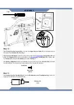
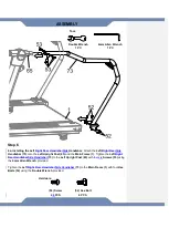
Page 23: ...1 ASSEMBLY Step 10 10a Connecting the Extension Wires Connect the Upper Console Cable 77 from the HFront Lower Handlebar 75 toto the Middle Sensor Cable 67 from the Left Upright Post 65 See Fig G Fig...

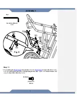
Page 24: ...Lower Console Bar Attach the Front Lower Console Bar 75 onto the both the Left Upright Post 65 and Right Upright Post 66 Tighten with twelve Screws 53 using the 6mm Allen Wrench provided Fig H Hardwa...

Page 25: ...the Front Lower Console Bar 75 Tighten with four Screws 51 using the Screwdriver provided See Fig J 12c Battery Installation Remove the battery cover from the rear of the Console 78 and install two A...

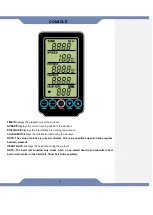
Page 26: ...ut CALORIES Displays the calories burned during the workout NOTE The value of calories is only an estimate This value should be used to track progress between workout HEART RATE Displays the heart rat...

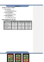
Page 27: ...CE or CALORIE goal a Pressing ENTER after setting a TIME goal will allow you to set a DISTANCE goal b Pressing ENTER after setting a DISTANCE goal will allow you to set a CALORIE goal 2 During a worko...

Page 28: ...etting range is 0 0 999 0 c Each increase decrease is 0 5 3 CALORIE COUNTDOWN a The preset value is 0 0 b The setting range is 0 0 9990 c Each increase decrease is 0 5 THE RANGE OF VALUE Preset Value...

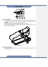
Page 29: ...d 2 Resistance Level 1allows the treadmill to go faster than level 7 3 The STOP position will lock the treadmill and not allow the belt to move 4 For any emergency pull the resistance lever all the wa...

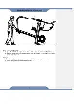
Page 30: ...e wheels make contact with the floor 2 Push or pull the unit to the desired location then gently lower the machine until it makes contact with the ground Storage 1 Store the elliptical in doors and in...

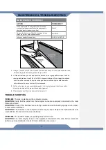
Page 31: ...as you can and squirt the silicone oil in a zigzag pattern across the entire running deck surface Use 30 50 ml of 100 silicone oil lubricant Do not apply the silicone oil on top of the running belt L...

Page 32: ...tions 4 Damage caused by normal wear and tear vandalism accidental or by animals 5 Any act of Nature such as fire flooding snow ice hurricane earthquake lightning or other natural disaster environment...

Page 33: ...______________________________________________________________ Night _________________________________________________________________________ SERIAL __________________________________________________...

Reviews: