background image

Safety Information  


Page 3 

Resonance Technology, Inc.                        CinemaVision System Installation / Operation Manual:  RTC-CVSS Rev 
12 


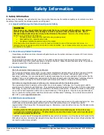
Only system components explicitly designated for use in the MRI suite should be placed inside the MRI suite.  
Components not designated for use inside the MRI suite may present a projectile hazard and can become airborne, 
causing property damage, serious bodily injury, or death.  Please refer to the installation block diagram to determine 
which components belong inside the MRI suite. 

Resonance Technology, Inc. will not be held liable for any injuries or property damage which may occur as the result of 
improper use or installation of this product.  By agreeing to this notice, users certify that they are familiar with basic 
safety procedures in an MRI room environment and that they have read and understand these safety precautions. 

For questions regarding installation procedures or this manual, Resonance Technology, Inc. technical support staff may 
be reached Monday through Friday 8 a.m. to 5 p.m., Pacific Standard Time at (818) 882-1997, or by email at 

support@mrivideo.com

2.5.


General Warnings for Electronic Products


Electric shock 

Failure to observe all operating and maintenance instructions may cause damage to this product and may result in 
property damage and/or injury or death from electric shock, fire, or other cause. 

To avoid the risk of electric shock or fire hazard, a multi-outlet power strip or extension cord should not be connected to 
the video monitor socket outlet on the CinemaVision controller. This socket outlet should only be used to power the 
CinemaVision video monitor provided with the system. 

Do not disassemble this product. 

Only Resonance Technology, Inc. trained, and authorized personnel should perform all required service for this product. 
Failure to comply with this warning may result in property damage, injury and/or death from electric shock, fire, or other 
cause. 

Avoid exposing this product to extreme environments. 

This product may be damaged by high temperatures, direct sunlight exposure, by dropping this product, or by other 
mechanical shock. Do not expose this product to rain or excessive moisture.  Avoid these conditions as the video goggle 
lenses may become damaged and may result in eye fatigue to the patient. 

Unplug this product when not in use for long periods of time. 

Always unplug this product when not in use for extended periods of time or during MRI maintenance.  Leave connected if 
used daily.  In addition, to prolong the life of the video goggle, use the Technologist Remote to turn off the power to the 
video goggle at night or when not in use.  Note that if the system is not used for 2 hours, it will hibernate and you may 
have to press the Tech Remote TALK button to wake up the system. 

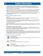
2.6.


Labeling Used to Indicate Device Safety 


Type BF Applied Part 

Devices that have conductive contact with the patient or have applied parts that are fixed in medium or long 
term contact with the patient. 


MR-Safe Device


Device considered 

safe

 for use anywhere inside the magnet room. 


MR Unsafe Device


Device considered 

unsafe

 for use in the MR room.  These items should not be taken inside the MR room 

due to being a projectile hazard in the magnetic field. 


Summary of Contents for Serene Sound

Page 1: ...nual Serene Sound A u d i o S y s t e m Resonance Technology Inc 18121 Parthenia Street Northridge California 91325 USA 1 818 882 1997 1 800 428 MRTV www mrivideo com Innovative Audio Entertainment 2...

Page 2: ...ral law restricts this device to sale by or on the order of a physician No part of the document may be photocopied or reproduced without the prior written consent of Resonance Technology Inc Informati...

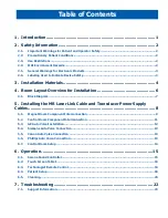
Page 3: ...allation 6 4 1 Block Diagram 7 5 Installing the MR Laser Link Cable and Transducer Power Supply Cables 8 5 1 Magnet Room Component Interconnection 9 5 2 Control Room Component Interconnection 11 5 3 G...

Page 4: ......

Page 5: ...t engineering We are confident this product will give you the tools you need for comforting the patient while undergoing MRI scans This installation operation manual outlines how to properly install a...

Page 6: ...may be purchased for this system With patient safety in mind Resonance Technology Inc recommends daily to weekly visual inspection on heavily used parts of the system like the Headset There is no set...

Page 7: ...the CinemaVision controller This socket outlet should only be used to power the CinemaVision video monitor provided with the system Do not disassemble this product Only Resonance Technology Inc train...

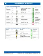
Page 8: ...rt Number Quantity Photo Description MR Safe Installation Location RTC 660 170 370 000 1 Serene Sound Controller Control Room RTC 660 050 535 000 1 Serene Sound Controller Power Supply Control Room RT...

Page 9: ...DH 1 Headset Hooks Magnet Room RTC 101 102 001 101 1 2 Channel MR Laser Link Cable Installed From control room to magnet room RTC 101 306 003 000 2 Hospital Grade AC Power Cord Equipment Room Control...

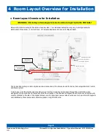
Page 10: ...Serene Sound Controller Technologist Remote Control and Stereo system A single Laser Link Fiber Optics cable bundle will run from the Serene Sound Controller through the penetration panel waveguide t...

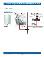
Page 11: ...4 1 Block Diagram Patient Headset Serene Sound Controller Tech Remote Control Penetration Panel Control Room Speakers Tablet Serene Sound Transducer Transducer Power Round to Round Cable Usually ran t...

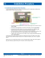
Page 12: ...ptical fibers will occur The routing of the transducer power cables will vary somewhat depending on the facility layout and the magnet type For most facilities and magnets the typical procedure would...

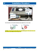
Page 13: ...ow Install the audio headset firmly into the Transducer using the bracket provided Be sure to connect the headset and fiber before powering on the unit Also make sure that the audio headset connector...

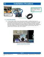
Page 14: ...atch the cable colors to those on the unit s labels Note Remember not to bend the individual cables smaller than a 15 cm radius WARNING Avoid creating loops in the cable as it may cause MRI image nois...

Page 15: ...er optic cable matches the color coded markings on the connection housing Optional Auto voice connection can be made in order to incorporate the MRI magnet Auto voice command features Connect the mini...

Page 16: ...uto Voice Connection 5 4 1 Remove the LINE OUT mini stereo audio cable from the back of the Siemens computer and plug it into the back of the AV console marked input using a mini stereo extension cabl...

Page 17: ...into the computer marked audio out 5 5 3 Be sure to test Auto Voice from Canon MRI System to make sure audio command signal is redirected to the RTC headset Be sure to set the Auto Voice volume level...

Page 18: ...d off To wake up the system just press down once on the TALK button of the Technologist Remote Control and wait for the system to synchronize completely Remember to always communicate with the patient...

Page 19: ...th device at a time If the Bluetooth cannot pair or connect is due to another device already paired with the Controller The Bluetooth sync button is on the front panel near top left corner of the spea...

Page 20: ...Console Controller operator volume settings It is possible that the Serene Sound Controller can lose sync pairing with the Bluetooth device when the unit goes to sleep 6 2 Touch Screen Tablet Resonan...

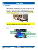
Page 21: ...d in the patient s audio headset lower the PTT Make sure all cables have been connected securely into the Transducer and that the components do not impede walkways Ensure that the Transducer is not pl...

Page 22: ...yes and adjust the headband NOTE the pivot should not be rotated more than 15 Position the headset microphone about 1 inch 2 5 cm away from the patient s mouth Your patient is now ready for your scan...

Page 23: ...n clockwise to increase the volume in the audio headset Rotate the black knob around the center button counterclockwise to decrease the volume in the audio headset 6 4 3 Inserting the Earbud tips The...

Page 24: ...r tips PN RTC 650 069 1521 X01 RTC recommends inspecting product before use Discard throw away ear plugs if they are damaged Ear tips are intended for single use only Use new pair of ear tips with eac...

Page 25: ...6 Operation Page 21 Resonance Technology Inc CinemaVision System Installation Operation Manual RTC CVSS Rev 12...

Page 26: ...p or fails to respond to the Technologist Remote Control commands Power down the Controller for approximately 10 seconds and then power up again If the system still does not respond Power down the com...

Page 27: ...respond check to see if the Transducer and Controller is syncing with one another Syncing is when the logo on the Transducer and the controller lights up and properly rotates clockwise For more infor...

Page 28: ...ts Our everyday pollution prevention activities reduce the need for electronic waste to go into landfills At Resonance Technology Inc we are committed to our customers our communities and to everyone...

Page 29: ...Notes Page 25 Resonance Technology Inc CinemaVision System Installation Operation Manual RTC CVSS Rev 12...

Reviews: