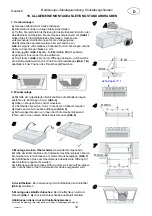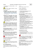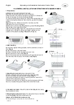
1. Preparations
2. Wall mounting
English
Operating- and Installation Instruction Cooker Hood
18.
GENERAL INSTALLATION INSTRUCTIONS STANDARD HOODS
a)
Using the supplied drilling template, drill the wall holes (4 holes 8
mm)
(Fig. 4)
b)
Insert the plugs in the drilled holes.
c)
Screw 2 screws into the top plugs up to ca.5 mm.
d)
Hang the hood on the screws
(Fig. 5)
e)
From the inside, pass the locking screws through the rear wall of
the hood and screw securely in the bottom plugs
(Fig.6)
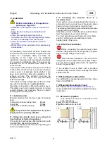
a)
Determine the exact location for the hood.
b)
Provide the power supply at the correct location.
c)
Now decide on the mode of operation (circulation or exhaust air
mode) and prepare the hood accordingly .
(Fig.1)
If you have decided upon exhaust air mode, all the appropriate core
holes for routing the exhaust air hose must be executed or already
present.
(Fig. 2)
shows the different variants for core holes and the
dimensions in mm to be observed.
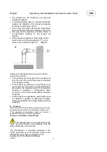
d)
Remove the inlet air mesh
(Fig. 3a)
resp. grease filter
(Fig. 3b)
for
later access to the inside of the hood.
e)
Mount the flange
(Fig. 1 A)
to the opening through which the
exhaust air is to be taken. (Where necessary change over the
positions of the plastic cap
(Fig. 1 B) and
the flange (A)
3. Mounting to a wall unit
(where intended for this)
Drill the underside of the wall unit using the drilling template.
Fix the hood inside the wall unit with 4 screws
(Fig. 7).
In the case of exhaust air hoods, an opening must be made in the
wall unit for the exhaust air pipeline.
Circulation air hoods do not require this opening because with these
the air is circulated through the slots at the front of the hoods.
Images are for illustration purposes only.
The form and fittings of your hood can vary from the illustrations.
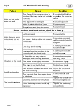
4. Circulation air mode :
Mount the carbon filter
(Fig. 8)
when using
the circulation air mode.
5. Mounting the exhaust air hose:
The exhaust air hose is mounted
to the flange
(Fig. 1 A)
with a metal hose clip.
see chapter 11.1
GB
fi200812atl
12

