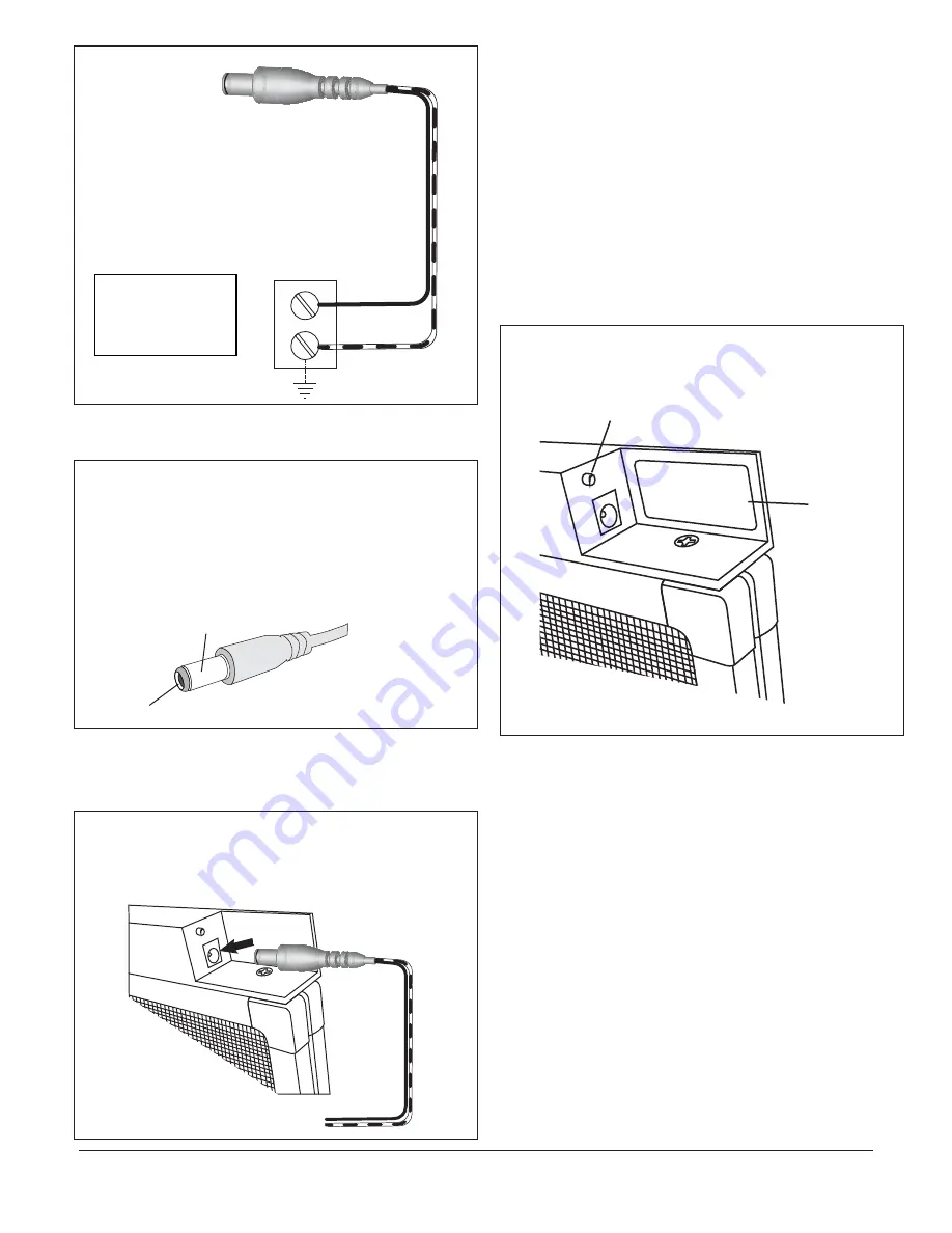
CONNECT THE WHITE
STRIPED WIRE TO THE
NEUTRAL/GROUND
TERMINAL
NEUTRAL/GROUND
24VAC TRANSFORMER
SOLID BLACK
WHITE STRIPE
24VAC
Connect
the
two stripped ends of the filter
power
cord
to
the
24V
transformer power supply
.
T
he
power cord
h
a
s
two
wires:
one
is
solid
bl
a
c
k
a
nd
the
other is
bl
a
c
k
with
a
white
stripe
.
(See
Figure
1)
.
Connect
the solid black
wire to
the
HO
T
termin
a
l
a
nd
connect
the white
striped wire
to
the
Neutr
a
l/Ground termin
a
l
.
Step 4)
Figure 1
3RCG-inst3-V3
1-866-876-8044 • 416-615-0214 • www.respicaire.com
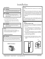
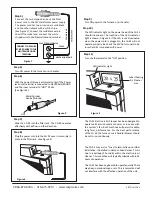
Figure 3
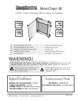
Metal Cylinder
LED Indicator Light
Label showing
Air Cleaner
Size
Neutral/Ground
HOT
Figure 2
Figure 3
T
urn ON
power
to the
f
urnace
or
a
ir
h
a
ndler
.
T
urn ON
power
to the
f
urnace
or
a
ir
h
a
ndler
.
The LED indicator light on the power head of the
CG 95
should illuminate. The loca�on of the LED indicator
light is shown in Figure 3. If the LED is not illuminated
when the power cord is plugged in, the
CG 95
will not
operate properly. Re-check the 24VAC terminals to be
sure the
CG 95
is supplied with power
.
Turn the thermostat to the “ON” posi�on.
The
CG 95
Electronic Air Cleaner has been designed to
operate either with constant power or in series with
the system’s fan. Both methods will permit reliable,
long term, performance. For the best performance
of the
CG 95
, the furnace or air handler blower should
be set to run con�nuosly.
The CG 95 may arc (or “snap”) electrically upon ini�al
installa�on, if installed in damp or humid areas. This is
due to a buildup of humidity within the electronic air
cleaner. This condi�on will typically subside within 24
hours of opera�on.
The
CG 95
has been engineered to operate quietly. There
may be an occasional snap or arc. This is normal and will
not interfere with the effec�ve opera�on of the unit.
With the power ON use a voltmeter to test if the Power
jack outer terminal is connected to NEUTRAL/GROUND
and the inner terminal to “HOT” 24 Vac.
(See Figure 2.)
Slide the CG 95 into the filter rack. The CG 95 operates
effec�vely with airflow in either direc�on.
Plug the power cord into the CG 95 once it is securely in
place in the filter rack. (See Figure 3)
Step 5)
Step 6)
Step 7)
Step 8)
Step 9)
Step 10)
Step 11)
20 x
25


