PART III ELECTRICAL SYSTEM OF THE UNIT
3-2
ENGLISH
Interlock switch
3.1 POWER CORD, FUSE AND INTERLOCK SWITCH
CONNETIONS
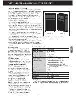
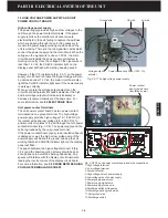
It is necessary for you to understand how the power cord, fuse and
interlock switch are connecting together before you learn the other
electrical system of the unit (Fig. 3.1-1).
1. Ground wire
: The ground wire of the power cord is securely
fixed at the metal bottom of the unit so that all the metal parts of the
unit is grounded.
2. Live line
: The white colour Live line of the power cord, at first,
goes through the fuse by wire connection and than goes to the
interlock switch, finally connected to the main circuit board. If there
is a short circuit in the unit, the fuse will be blown out to protect the
whole machine. When opening the front panel, the interlock switch
will work and interrupt the Live line at once.
3. Neutral wire
: The Neutral wire of the power cord directly goes
through the interlock switch and goes out to the main circuit board.
When you open the front panel the interlock switch will also
interrupt the Neutral wire at once to protect people touching the
electrical parts of the unit.
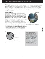
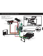
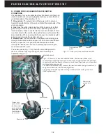
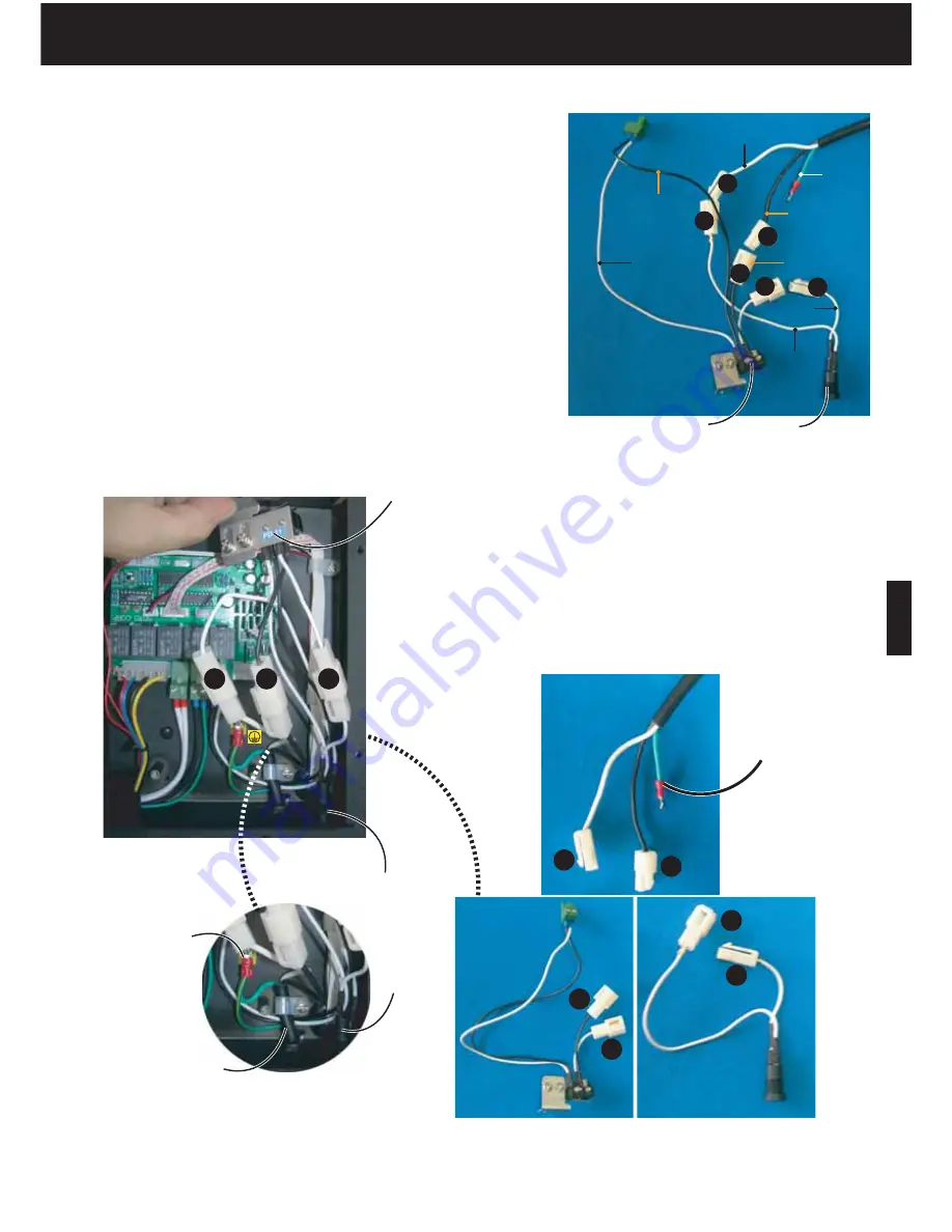
The below picture (Fig. 3.1-2) shows the wire arrangement in
the unit. It will be easy for you to figure out the wires if you
understand Fig. 3.1-1.
Fig. 3.1-1 Power cord, fuse and interlock switch.
Fig. 3.1-2 Power cord, fuse and interlock switch. The Live line (White color)
connects the fuse through connector 1# and connects the interlock switch through
connector 2# and then goes into the main circuit board (Right side pin at the power
cord connection, green color).
The Neutral wire (Black color) connects the interlock switch through connector 3#
and goes into the main circuit board (Right side).
The green ground wire of power cord is grounded with the motor ground wire
(Yellow green color).
Fuse holder
Fuse holder
1
2
1
Live wire
into fuse
Live wire
out fuse
Live wire out
interlock switch
into PCB1
Fuse
Neutral
wire
Neutral wire
into interlock
switch
Neutral wire out
interlock switch
into PCB1
Twin interlock
switch
Ground
wire
Live line
Power cord
connector
1
1
2
2
3
3
2
3
Power cord
Power cord
ground wire
and fan motor
ground wire are
grounded to the
metal bottom
by a screw.
Power cord
ground wire
1
3
2
3
To PCB1
Summary of Contents for R200T
Page 69: ...ENGLISH NOTES ...

