PART III ELECTRICAL SYSTEM OF THE UNIT
3-4
ENGLISH
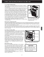
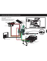
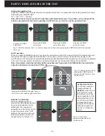
3.2 ELECTRICAL CIRCUIT BOARDS
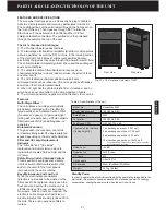
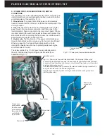
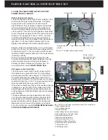
The main circuit board and the display circuit board
are most important parts of the unit. Pressing any
buttons on the control panel will control the main
circuit board through the display circuit board wire for
the unit to carry out the desired functions. There will
no display lights or incorrect display on the display
panel if the display circuit board wire connections are
loosened, the main circuit board or display circuit
boards are broken (Fig 3.2-1).
Buttons
Main circuit board
Remote
receiver
Odor sensor
Display circuit board wire
Fig. 3.2-1 Main circuit board / display circuit board
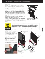
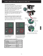
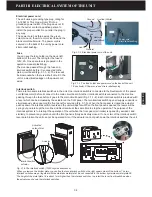
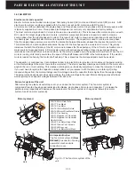
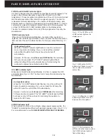
Relay
Fan motor
connection
Reset
button
Melody
chip
Memory chip
Microprocessor
Power supply
singnal wire
connection
Speaker
connection
-Do not touch this area of circuit
board with hand when the unit is
on, the voltage in this area is 120V
ac. If not, electrical shock or
personal injury will occur.
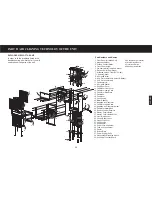
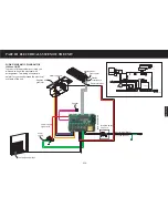
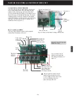
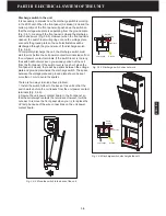
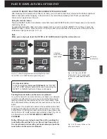
Main Circuit Board (PWB1)
The main circuit board is secured by four plastic
stand-offs at the bottom of the unit.
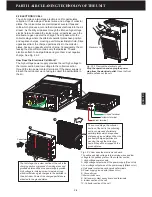
Power cord connection
Transformer
UV lamps connection
1
1
Fig. 3.2-2 Main circuit
board and connections.
See Wiring Schematic on
page 3-1.
Integrated circuit (IC) is also
known as a chip.
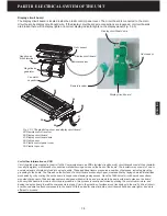
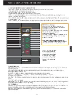
Display
circuit board
(PWB3)
Negative ion
generator
connector
Display circuit
board connection
High voltage power
supply connection
Summary of Contents for R200T
Page 69: ...ENGLISH NOTES ...

