PART III ELECTRICAL SYSTEM OF THE UNIT
3-8
ENGLISH
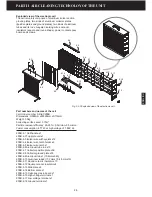
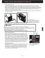
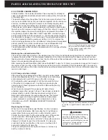
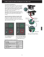
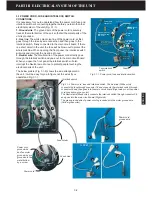
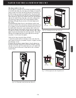
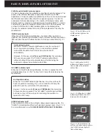
Discharge switch in the unit
It is necessary to discuss how the discharge switch is working
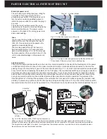
in the 200T unit. When the front panel (Air intake) is closed the
bottom portion of the front panel will push down the switch so
that the voltage wire plate is separating from the ground plate
(Fig. 3.4-1), meaning if the front panel is closed the discharge
switch does work (Fig.3.4-3). However, when the front panel is
opened, the switch lever will spring out and the voltage plate
connects the ground plate so the cell electrostatics will be
discharged through the ground wire of the discharge switch
(Fig. 3.4-4).
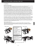
To completely discharge the cell, the discharge switch must
start to work before the cell power contact terminals leave from
the unit power contact terminals. If the switch lever is too long
the switch will not work even you already pulled out the cell
from the front panel. If the switch lever is too short, when the
front panel is closed, there will be a spark between the voltage
plate and ground plate inside the discharge switch. The space
between the voltage plate and ground plate should be kept
more than 7 mm to avoid the sparks.
There are two ways to solve above problem:
1. Install the switch further to the back of the unit so that the
switch works before the cell leaves from the unit power contact
terminals (Fig. 3.4-5).
2. Secure the unit power contact board to the front panel so
that the cell always contacts the terminals. However, it will be
not easy to remove the front panel when you try to replace the
UV lamp because of the wire connections on the unit power
contact board.
Low voltage
Separated
Ground
Switch
not working
Low voltage
Ground
Short circuit
Switch
working
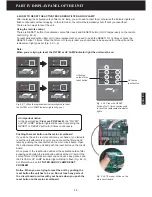
Fig. 3.4-3 Discharge switch does not work.
Fig. 3.4-4 Discharge switch discharges the cell.
Fig. 3.4-5 Move the switch to the back of the unit.
Summary of Contents for R200T
Page 69: ...ENGLISH NOTES ...

