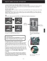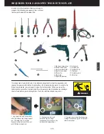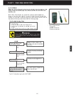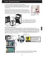
PART III ELECTRICAL SYSTEM OF THE UNIT
3-10
ENGLISH
3.6 FAN MOTOR
Electric motor and capacitor
Electric motors can be divided into two types: Alternating Current (AC) motors and Direct Current (DC) motors. A DC
electric motor will not run when supplied with AC current, nor will an AC motor run with DC current.
AC motors are further subdivided into single phase and three phase motors. Single phase AC electrical supply is what
is typically supplied in a home. Three phase electrical power is commonly only available in a factory setting.
The most common single phase AC motor is known as a universal motor. This is because this motor can also run with
DC current. For larger single phase AC motors, a electrical component known as a capacitor is used to create a
second phase from the single phase AC current. This type of AC motor is known as an induction motor and there are
two basic types; a capacitor start motor and a capacitor run motor
.
The capacitor is used to create a second phase
from the single phase power source and it is the interaction between these two phases that causes the motor to turn.
This introduction of a second phase eliminates the need for the brushes used in a universal AC motor. This greatly
increases the both the efficiency of the AC motor and increases the life expectancy of the AC motor as brushes are a
major source of wear and failure. AC motors also come with various speed ratings. Speed is usually specified as
rotations per minute (RPM) at no load condition. As the motor is loaded down, the speed will slow down. When the AC
motor is running at its rated power draw, the speed of the shaft measured in RPM is the full load speed. If the electric
motor is loaded too heavily, the motor shaft will stop. This is known as the stall speed and should be avoided.
The capacitor, or condenser as it is sometimes called, in an electric motor provides a time delay on the power arriving
at the start windings of the motor to make the motor start. The start or auxiliary windings are inserted in the motor at an
angle to the run or main winding. This creates a starting torque - basically something to make the rotor want to rotate.
If you ever need to replace the capacitor, always make sure you replace it with the same micro farad (uF) rating.
Induced voltages from the motor windings result in voltage across the capacitor that is higher than the supply voltage.
The actual value depends upon the supply voltage, the motor windings & the load. Motors driving pumps at full load
would typically see capacitor voltages between 320- 440 volts.
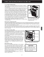
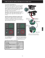
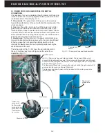
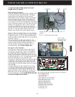
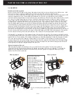
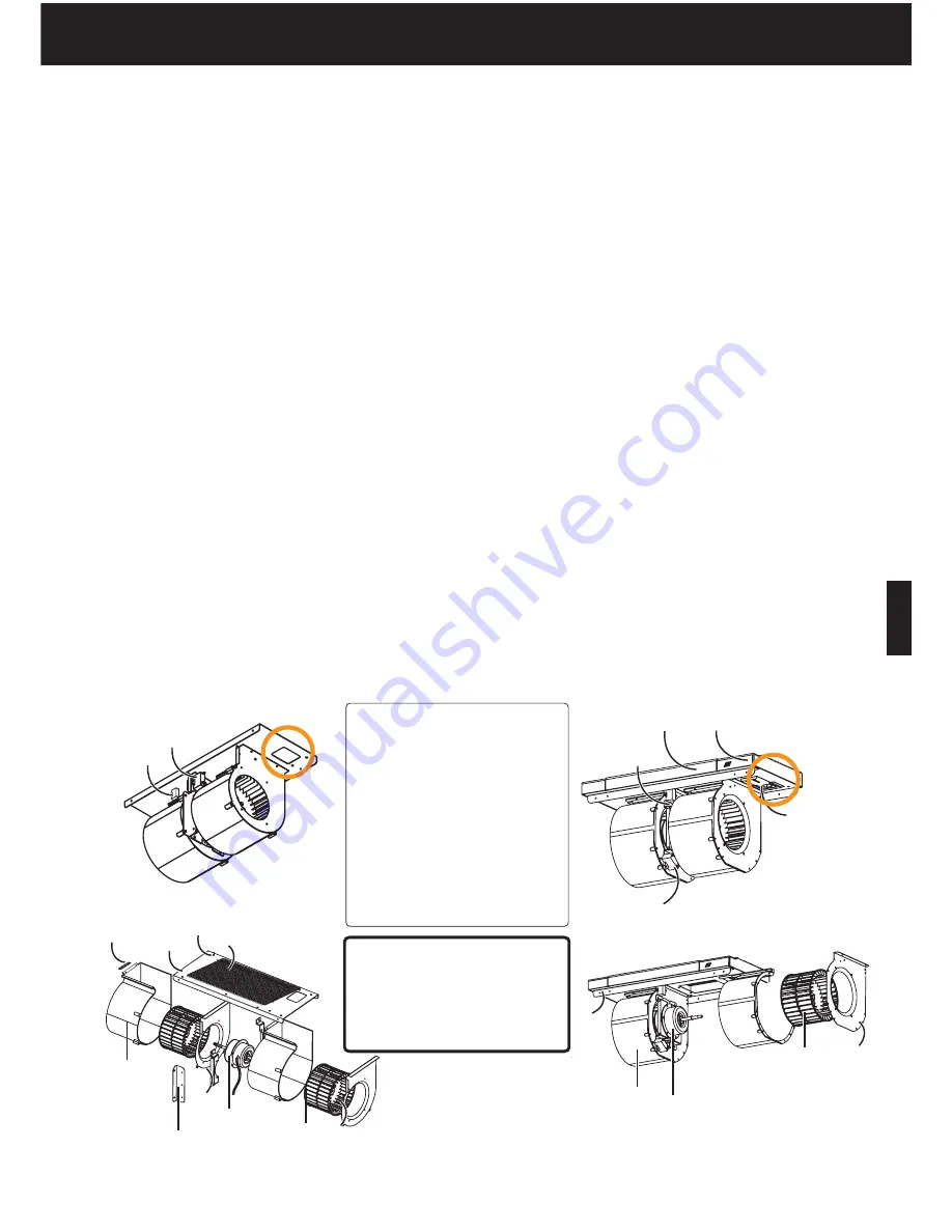
Fan motor system of the unit
After removing the plastic air outlet top cover, you can see the fan motor system. The fan motor system is
composed of two fan housings and radial type fan blades, single phase AC motor and capacitor. To increase the
particle removal capability and decrease the noise levels, the motor system is changed as follows (Fan motor
system-A and Fan motor system-B).
200-16. Motor Side Plate
200-17. Fan Blade
200-18. Fan Motor
200-18.1 Motor Metal Fixture
200-18.2 Motor Wires Metal Fixture
200-19. Fan Housing
200-21. Negative Ion Generator
200-23. Negative Ion Generator
Plastic Holder
200-22. Fan Motor Upper Plate
200-22.1 Black Color Screws
200-22.2 Wire cover
200-24. Fan Motor Metal Mesh
21
20
23
17
18
18.2
18.1
22
22.1
24
19
16
21
30
29
20
22.2
17
22
19
16
18
Motor system-A
Motor system-B
An important notice:
The fan motor system-B
(From
R200xxE)
has new fan housing,
new metal mesh and wire
connection cover.
Fig. 3.6-1 The fan motor system of the
unit.
Summary of Contents for R200T
Page 69: ...ENGLISH NOTES ...

