PART V TROUBLESHOOTING
5-10
ENGLISH
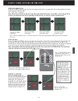
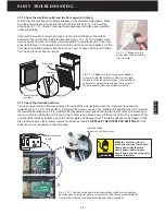
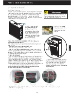
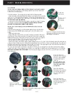
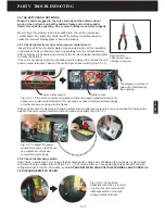
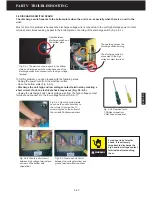
Fig. 5.2.2-3 Check the high and voltage output of the power supply. Place
the ground clip of the high voltage probe on the unit ground terminal and
connect the probe each to high voltage and low voltage terminal.
1-Ground terminal
2-Low voltage terminal
3-High voltage terminal
5.2.2 Check the power supply and the main circuit board
If the CHECK indicator light still flashes after you remove the cell ,
go ahead to check the high voltage power supply.
Check the high voltage output of the power supply
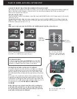
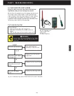
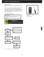
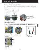
- Have your high voltage probe ready. Red to red voltage ohmmeter
input and black to black. The high voltage probe shown is 1000:1,
meaning 1000 volt at the probe should be 1 volt dc at ohmmeter.
- Set the ohmmeter in voltage DC range of 20V (Fig. 5.2.2-1).
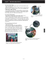
- Open the bottom plate and make sure the power supply
connections are connected tightly (Fig.5.2.2-2).
Caution: Do not touch the unit power contact terminals
without discharging the power contact terminals!
- Place the black of the ohmmeter on the unit ground terminal and
red one on high voltage or low voltage terminal (Fig. 5.2.2-3).
- Check the output of the power supply. The high voltage should
read 7.3~7.8KV and the low voltage will be 3.5~4.5 KV when there
is a cell in the unit. If it reads less than 6.0 KV or no voltage, you
will have to further investigate other reasons.
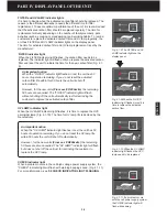
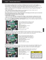
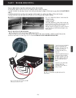
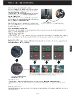
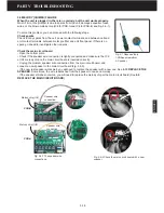
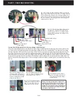
Fig. 5.2.2-4 After fastening the connections, check the voltage output of the main
circuit board to the power supply. It should read close to 120V ac. If not, replace the
high voltage power supply.
1-Power supply connection
2-Power supply cord connection
3-Power supply signal wire connection
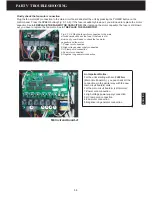
Check the main circuit board
If there is no voltage on the high or low voltage terminal, go ahead to check the
main circuit board voltage output to the power supply.
- Set the ohmmeter in the range of 200V ac.
- Make sure the front panel is closed correctly.
- Check the output voltage from the main circuit board to input of the power
supply. It should read somewhere close to 120V ac. If the reading is no voltage,
you have to change the main circuit board. See
6.6 REPLACE THE MAIN
CIRCUIT BOARD
. If the output voltage of the main circuit board is close to 120V
ac and connections 2# and 3# are fastened tightly, you have to change the
power supply with a new one (Fig.5.2.2-4). See
6.3 REPLACE THE POWER
SUPPLY
.
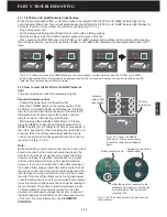
Fig. 5.2.2-2 Lay down the unit
horizontally on the soft mat.
Unscrew the 10 screws located
on the bottom of the unit with
Phillips screwdriver.
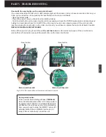
Fig. 5.2.2-1 Prepare the high voltage probe and
ohmmeter. Set the ohmmeter in 20V dc voltage
range.
1
2
3
1
2
3
1
2
3
Summary of Contents for R200T
Page 69: ...ENGLISH NOTES ...

