WIREFREE P
ASSIVE
INFRA RED MOVEMENT
DETECTORS (PlR’s)
T
wo Passive Infra Red Movement Detectors are supplied
in the standard package. However, additional Passive
Infra Red Movement Detectors can be purchased
separately, if required. Passive Infra Red Movement
Detectors are designed to detect movement within a
protected area. The detector element detects differences
in Infra Red radiation when a person moves within the
protected area. If movement is detected, a radio signal is
transmitted to the Solar Siren to activate the alarm.
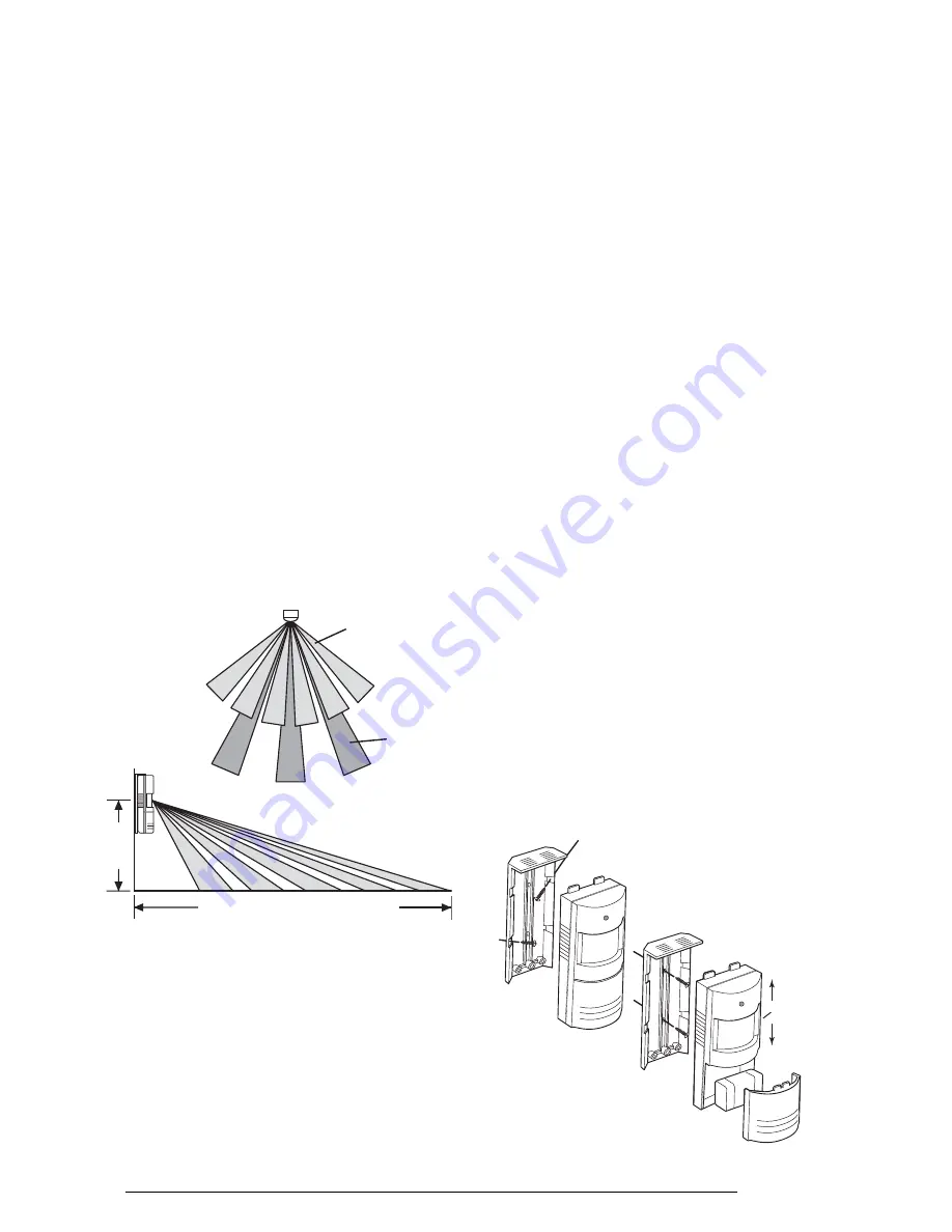
The recommended position for a Passive Infra Red
Movement Detector is in the corner of a room mounted
between 2 and 2.5 metres from the floor. At this height,
the detector will detect movement up to 6 metres at
110° and 12 metres at 60° depending on adjustment.
Also, in this position, the 110°/60° fan-shaped detection
patterns can normally offer greater protection than
mounting on a flat wall. Before selecting a position for
a Passive Infra Red Movement Detector the following
points should be noted:
1. Do not position the detector facing a window or
direct sunlight. PIR Movement Detectors are not
suitable for use in conservatories or draughty areas.
2. Do not position the detector directly above any
source of heat, eg. fire, radiators, boiler etc.
3. Where possible, keep pets out of areas protected
by Passive Infra Red Movement Detectors. If this
is not possible, alternative mounting arrangements
may be required.
4. Where possible, mount the detector so that the
logical path of an intruder would cut across the fan
patterns rather than directly towards the detector.
Any number of PIR Movement Detectors can be used
with your system, providing they are all coded with the
System House Code and are within the radio range of
the Solar Siren. To install and set the PIR Movement
Detector, proceed as follows.
INST
ALLING THE WIREFREE
PASSIVE INFRA RED MOVEMENT
DETECTORS (PIR’s)
1.
Remove the battery cover by inserting a coin
under the cover lip and twisting open. Remove the
fixings pack.
2. Remove the screw (in the battery compartment)
holding the wall bracket to the detector.
3. Slide the bracket up and remove the wall bracket
from the detector as shown.
4. Hold the wall bracket in position and mark the
two mounting holes. (If corner mounting, drill pilot
holes in the chamfers as shown).
5. Drill two 4mm diameter holes and insert the plastic
wall plugs supplied.
6. Screw the bracket to the wall using screws
supplied.
7. Offer the detector up to the wall bracket and locate
it into one of the bracket slots to angle the detector
down slightly. Fix the detector in position on the
bracket using the fixing screw at the rear of the
battery compartment.
6
Eclipse E100
110
°
angle
60
°
angle
Up to 6m at 110
°
and 12m at 60
°
2-2.5m
Pulse Count
Detection
Switch on
Side
UP = 2
pulse
detection
DOWN = 1
pulse
detection
TOP
TOP
Fixings for
Corner Mounting
Fixings for
Surface Mounting


