background image

The Solar Siren & Strobe contains a sophisticated radio

receiver.  However, reception of radio signals can be

affected by the presence of metallic objects within the

vicinity of the Solar Siren & Strobe.  It is therefore

important to mount the Solar Siren & Strobe a minimum

distance of 1m radius away from any external or internal

metalwork, ie. external drainpipes, gutters and internal

radiators, mirrors etc.

INSTALLATION

Remove the holding screw from the base of the housing

and carefully hinge off the front cover.  All electronic

components are housed within the front cover.

Use the rear backplate as a template to mark the

position of the four fixing holes on the external wall.

Drill four 5mm diameter holes and insert the plastic

wall plugs.  Mount the backplate using the four

screws provided.

SETTINGS

Undo the 3 screws holding the dip switch cover in

place and remove the cover.

SIREN CODE

To enable the Control Unit to operate and control the

external Siren & Strobe you need to set a Siren Code

in the Solar Siren, which will also be programmed into

the Control Unit during programming.

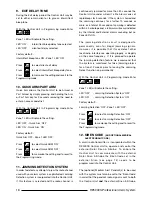
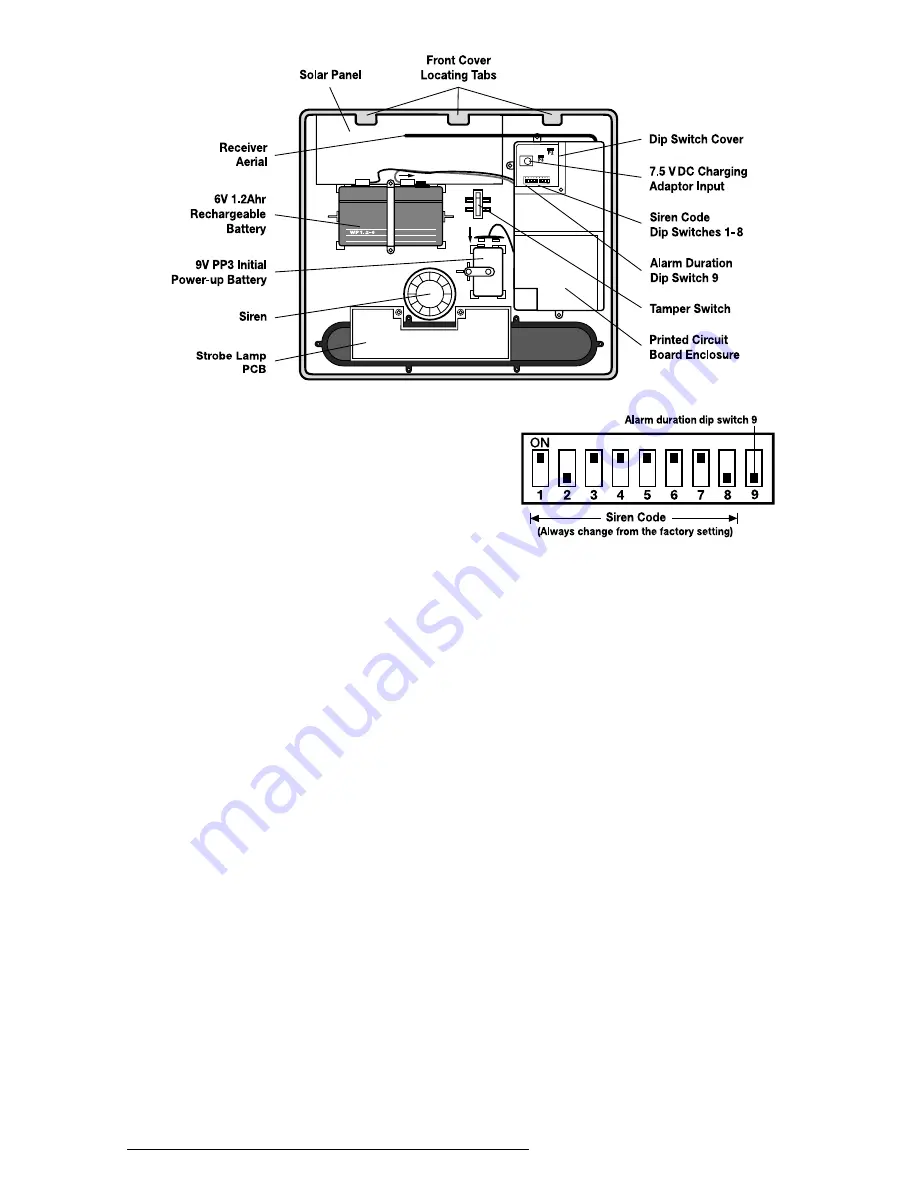
Using a ball point pen set the miniature dip switches

1-8 to a random sequence of ‘ON’s’ and ‘OFF’s’.

Make a note of the Siren Code dip switch settings as 

this will be needed when programming the Siren

Code into the Control Unit.

Note:  When the Siren & Strobe is viewed as shown

above (solar panel at top) the dip switches are 

‘upside down’.

ALARM DURATION

This is the maximum length of time that the Solar

Siren & Strobe alarm will sound for, following

activation.  Alarm duration can be set for either 3 or

15 minutes.  Set dip switch 9 ‘OFF’ for 3 minutes or

‘ON’ for 15 minutes.

Refit the dip switch cover securely.

Note:  Following activation into alarm condition the

Solar Siren & Strobe will continue to sound until either

the Control Unit is Disarmed, or the Control Unit

autostop time expires, or until the Siren & Strobe

alarm duration time expires; whichever occurs first.

INITIAL POWER-UP

Once you have completed setting your Siren Code

and alarm duration time, connect the 9V PP3 initial

power-up battery to the clip-on connectors.  Connect

the rechargeable battery to the charging leads red to

red (+) and black to black (-).

14

RE5000S Professional Alarm System

View of inside Solar
Siren & Strobe

Summary of Contents for RE5000S

Page 1: ... Wireless Intruder Alarm System includes 1 x Solar Wireless Siren and Strobe 1 x Control Unit 1 x Passive Infra Red Detector 1 x Magnetic Contact Detector 1 x Remote Control 1 x Power Supply INSTALLATION OPERATING HANDBOOK INSTALLATION OPERATING HANDBOOK ...

Page 2: ...re proceeding with the installation During installation it is important that the installer follows the procedures in sequence All components with the exception of the external Solar Wireless Siren Strobe are suitable for indoor use only This manual should be retained by the user for future reference Tools and Equipment Required 150mm flat blade screwdriver 150mm cross head screwdriver Hammer Drill...

Page 3: ... 14 PROGRAMMABLE FUNCTIONS House Code 15 Instant Delay Zone 16 Page No PROGRAMMABLE FUNCTIONS cont Exit Delay Time 16 Alarm Autostop Time 16 Main User Access Code 16 Door Chime Zone 17 Entry Delay Time 17 Part Arm Zone Omit 17 Exit Delay Tone 18 Quick Arm Part Arm 18 Jamming Detection System 18 Siren Code 18 Second User Access Code 19 EXTERNAL CONNECTIONS 19 OPERATING INSTRUCTIONS Fully Arming the...

Page 4: ...so incorporates a sophisticated Jamming Detection Circuit with Jamming Counter and pre alarm indication A Zoneable Door Chime Quick Arm Operation and Walk Test Facilities are also selectable via the Control Unit The RE5000S Wireless Intruder Alarm package contains all the components necessary to install a complete Intruder Alarm System within your premises You can increase your protection by addin...

Page 5: ...manual All necessary fixings Window warning stickers Solar Wireless Siren Strobe incorporating rechargeable battery Rechargeable Batteries fitted in the Control Unit and the Siren Strobe Detector and Remote Control Alkaline Batteries Wireless Passive Infra Red Detector RE5000P Wireless Standard Magnetic Contact Detector RE5000M Wireless Remote Control RE5000R ...

Page 6: ...STEM PART ARM Protect either all of your home or just the areas you choose For example for night time protection you can have downstairs plus the garage and shed ON whilst upstairs is OFF This allows you to occupy upstairs areas without activating your alarm PLANNING YOUR INSTALLATION Before attempting to install your RE5000S Wireless Alarm System it is important to study your security requirement...

Page 7: ...et or fused connection unit Note Ensure that the adaptor will not be removed from the socket or accidentally switched off when the system is in use 3 The Control Unit should be close to the entry exit door but not visible from the door or windows 4 Do not locate the Control Unit closer than 1 metre to any large metallic object eg mirrors radiators fridge freezers etc 5 Locate the Control Unit in a...

Page 8: ...mark and drill 2 x 4mm diameter holes insert the wall plugs and secure the adaptor to the wall using the fixing bracket and double sided tape 2 Remove the battery compartment cover and back up battery Lead the adaptor DC output cable along the Cable Channel in the rear of the Control Unit and plug the jack plug into the jack socket in the battery compartment 3 Plug the 13A plug into a local socket...

Page 9: ...it in the event of a failure of the mains supply The Back up Battery is capable of providing emergency power to the Control Unit for a period of approx 8 hours and will automatically recharge on restoration of the supply 1 To fit the Back up Battery connect the battery leads red to red and black to black and place the battery into the battery compartment 2 In the event of a mains failure the green...

Page 10: ...in your system Note miniature switches 7 and 8 do not form part of the House Code and should be set in the position in the Remote Control Take care not to touch the printed circuit board or allow dust or moisture to enter the Remote Control Unit as this may damage the electronic components 4 Reassemble the two halves of the unit and secure using the fixing screw SETTING THE CONTROL UNIT HOUSE CODE...

Page 11: ...at the Control Unit acknowledges the signals by emitting the two tone chime and flashing the Medical Alert Zone 8 LED for 3 seconds The Control Unit should be left in Test mode whilst the detectors and other accessories are set up and installed However if you wish to exit the Test mode press and hold the button until the unit emits 2 bleeps and the Arm Part Arm LED s extinguish SYSTEM ZONING The R...

Page 12: ...on a flat wall Before selecting a position for a Passive Infra Red Detector the following points should be noted 1 Do not position a Detector facing a window or direct sunlight Passive Infra Red Detectors are not suitable for use in conservatories or draughty areas 2 Do not position a detector directly above any source of heat eg fire radiators boiler etc 3 Where possible keep pets out of areas pr...

Page 13: ...ector as shown 3 Hold the wall bracket in position and mark the two mounting holes For corner mounting drill pilot holes in the wall bracket chamfers as shown 4 Drill two 4mm diameter holes and insert the plastic wall plugs supplied 5 Screw the wall bracket to the wall using the screws supplied 6 Position the Detector on the locating pin and slide down then fix the Detector to the wall bracket usi...

Page 14: ...ny number of Magnetic Contact Detectors can be used with your system providing they are all coded with the system House Code and are within radio range of the Control Unit Magnetic Contact Detectors can be fitted to protect doors or windows as required To set the House Code and fit the battery proceed as follows ENSURE THAT THE CONTROL UNIT IS STILL IN TEST MODE 1 Remove the battery cover by slidi...

Page 15: ...ed and normally open circuit inputs in addition to the standard Contact Detector operation Refer to page 27 for further details Once you have completed installing all your Detectors take the Control Unit out of Test mode by pressing and holding the button until the Control Unit emits 2 bleeps and the Arm Disarm LED s extinguish INSTALLING AND SETTING THE EXTERNAL SOLAR WIRELESS SIREN STROBE The So...

Page 16: ...so be programmed into the Control Unit during programming Using a ball point pen set the miniature dip switches 1 8 to a random sequence of ON s and OFF s Make a note of the Siren Code dip switch settings as this will be needed when programming the Siren Code into the Control Unit Note When the Siren Strobe is viewed as shown above solar panel at top the dip switches are upside down ALARM DURATION...

Page 17: ...mmable functions have a Default setting it is important that each function is selected and set to the user s requirements on initial installation The Control Unit has an initial Default Main User Access Code the code that operates the system of To enter the Programming mode and change each programmable function proceed as follows Enter The Full Arm and Part Arm LED s will illuminate and all the Zo...

Page 18: ...e the setting and to revert to the Programming mode 4 ALARM AUTOSTOP TIME This is the length of time that the alarm will sound for when activated A fully silent alarm option is also available If accidentally triggered the alarm can be stopped at any time using the Remote Control or by disarming at the Control Unit keypad Note The maximum length of time that the external Solar Siren Strobe will sou...

Page 19: ...he number of the Zone to illuminate or extinguish the appropriate Zone LED Press to memorise the setting and to revert to the Programming mode 7 ENTRY DELAY TIME When entering an entry delay Zone with the system Armed or Part Armed the system will be inactive for a preset Entry Delay time to allow you time to disarm the system by entering your access code at the Control Unit or using the Remote Co...

Page 20: ...nd the Jamming continues for a further 10 seconds or more or a total of 30 seconds of Jamming is detected within a 5 minute period a full alarm will occur indicated by the Internal and External alarms sounding but no Zone LED s ON The jamming detection circuit is designed to permanently scan for illegal jamming signals However it is possible that it may detect other local radio interference operat...

Page 21: ...or re programming only However you plan to use the system for security reasons it is essential that you change the Second User Access Code to another four digit number which only you and other users of the system will know and use Again a number with a personal significance will be easier to remember With the Control Unit in Programming mode Enter No Zone LED s will be illuminated Enter your new S...

Page 22: ...eas not protected by Passive Infra Red Detectors or that suitable precautions have been taken to allow for pets The system may be fully armed either at the Control Unit or using a Remote Control If Arming at the Control Unit you must first Enter your 4 digit Access Code Main User or Second User Code then press Alternatively if Quick Arm has been programmed press and hold the button for 5 seconds I...

Page 23: ...t and entering your 4 digit Access Code Main User or Second User Code followed by Note If the system is not disarmed during the Entry Delay Period a full alarm will occur When using the Remote Control Unit you may be able to disarm the system from outside the premises before entering Establish the operational range of the Remote Control Unit before using this method DISARMING AFTER AN INTRUSION A ...

Page 24: ...s not illuminate the battery needs to be replaced In the event of a low battery condition clear the low battery indication then set the Control Unit to Test mode see page 9 Replace the battery as required and ensure that the Test chime is emitted when the battery is inserted Remember to take the Control Unit out of Test mode when you have finished Note When replacing PIR Detector batteries fit PP3...

Page 25: ...e batteries connected unless the unit is able to receive sufficient light to maintain the battery charging circuit Failure to maintain charge to the unit will result in the rechargeable battery running unacceptably low Should this occur the unit must be recharged from a 240 7 5V dc mains adaptor Response order code S100TR When re powering the Solar Siren Strobe fit a new 9V PP3 leak proof alkaline...

Page 26: ...at Personal Attack Button Medical Alert Pendant or Smoke Detectors have not been operated 4 Check that battery covers on all detectors are fitted securely 5 Check for Jamming Detection Alarm operation Control Unit not working Mains light is off 1 Check that mains adaptor is plugged in connected and switched on Control Unit will not function Sirens are sounding 1 Disconnect power including Control ...

Page 27: ...rom the floor depending on the size of pet Passive Infra Red Detector flashes when you walk past it 1 Low battery replace alkaline battery Passive Infra Red Detector false alarming 1 Ensure that the Detector is not pointing at a source of heat or a moving object 2 Ensure that the Detector is not mounted above a radiator or heater 3 Ensure that the Detector is not facing a window or in direct sunli...

Page 28: ...m System has been installed giving details of at least two persons who know the Access Code s or are in possession of a Remote Control Unit 2 Ensure that all users are aware of the operating procedures 3 Inform the local Environmental Health Authority of the installation and which police station has been informed 4 Immediately inform your local police station if there is a change to the persons wh...

Page 29: ...the Control Unit would be received by both Siren Strobes simultaneously DUMMY SIREN STROBE RE5000D Alternatively the Siren Strobe is available as a Dummy design and acts as an excellent visual deterrent MAGNETIC CONTACT DETECTOR WITH HARD WIRED INPUTS RE5000MHW In addition to the features and benefits of the standard RE5000M Magnetic Detector this unit also incorporates facilities for hard wiring ...

Page 30: ... a fire signal has been received by the Control Unit SECURITY DIALLER RE5000AD Connects directly to your standard telephone line to automatically dial for help upon alarm activation Incorporates facilities for storing up to 4 x 24 digit telephone numbers and 3 separate trigger inputs messages for intruder fire and medical alert Ideal for informing neighbours or relatives of an alarm condition Note...

Page 31: ...tting or use local radio interference wilful or accidental damage or any consequential loss or damage howsoever caused This guarantee does not affect your statutory rights If an item develops a fault the product must be returned to the address below in adequate packaging with 1 A copy of your original invoice receipt 2 A full description of the fault 3 All relevant batteries PLEASE NOTE If returni...

Page 32: ...ith payment Full written confirmation of acceptance will be forwarded to you by return of post IMPORTANT Return your Extended Warranty Application Form below with your Guarantee Registration to give a total of five years cover IMPORTANT PLEASE REGISTER YOUR GUARANTEE WITHIN 14 DAYS OF PURCHASE DELIVERY ADDRESS if different Postcode Telephone RE5000S Response Electronics Plc are a leading supplier ...

Page 33: ...e Draw Rules Either fill in your details overleaf and return the GUARANTEE REGISTRATION FORM WITH the ENCLOSED PRIZE DRAW OFFER SHEET within 14 days to Response Electronics Plc Guarantee Registration Department FREEPOST KT4437 Epsom Surrey KT19 9BR ALTERNATIVELY you can register your Guarantee online via www responseplc com where you will automatically be entered into our current Prize Draw ...

Page 34: ...P Detection range up to 5m at 180 and 14m at 110 Walk test facility RF Immunity Temperature Compensation Low Battery Indication Anti Tamper Wall Bracket corner or flat surface mount Alkaline Battery supplied Remote Control Order Code RE5000R Disarm Part Arm Full Arm Personal Attack Alkaline Battery supplied Key Ring fixing Security Dialler Order Code RE5000AD Input Voltage 11 5 14V dc Current cons...

Reviews: