INSTALLATION
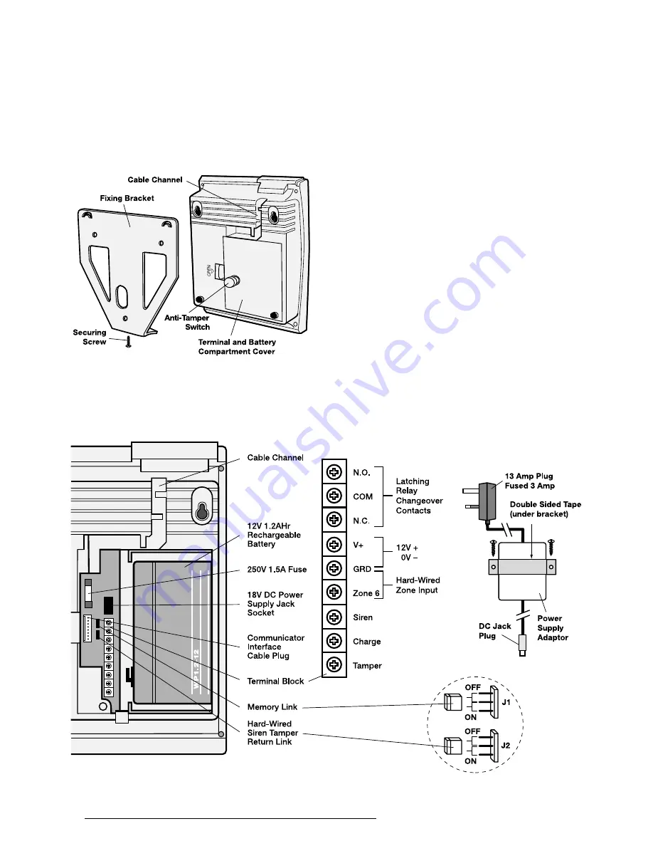
Remove the fixing bracket securing screw and slide
the fixing bracket off of the keyhole slots at the top
of the Control Unit. Hold the fixing bracket level in
position on the wall and mark the 3 fixing bracket
holes on the wall. Drill 3 x 4mm diameter fixing holes;
fully insert the plastic wall plugs supplied and secure
the bracket to the wall using the three fixing screws.
An in-line DC Mains Adaptor and Cable are supplied
with the Control Unit. To connect the Mains Adaptor
proceed as below:
1. Select a suitable location for the Mains Adaptor
(eg: a mains supply cupboard). Using the adaptor
fixing bracket as a template, mark and drill 2 x
4mm diameter holes, insert the wall plugs and
secure the adaptor to the wall using the fixing
bracket and double sided tape.
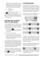
2. Remove the battery compartment cover and back-
up battery. Lead the adaptor DC output cable
along the Cable Channel in the rear of the Control
Unit and plug the jack plug into the jack socket in
the battery compartment.
3. Plug the 13A plug into a local socket. Alternatively,
the plug can be removed and the mains lead
connected to a fused connection unit (fused 3
amps) as follows:-
The wires in the mains lead are coloured in
accordance with the following code:
NEUTRAL
= Blue
LIVE
= Brown
If the colours of the wires in the mains lead do
not correspond with the markings identifying
6
RE5000S Professional Alarm System
Rear view of Control Unit/Fixing Bracket
View inside Terminal/Battery Compartment


