background image

9

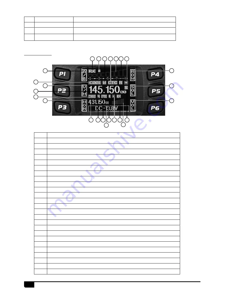
4.3 Display

NO.

Key

Functions

1

Antenna connector Connect a 50 ohm antenna

2

Ex-Speaker Jack

Connect external speaker

3

Power cable

Connect a standard DC power cable

NO. Functions

1

Displays the self define function when press P1

2

Displays the self define function when press P2

3

Displays the self define function when press P3

4

Displays the self define function when press P4

5

Displays the self define function when press P5

6

Displays the self define function when press P6

7

Displays the main channel TX or RX status

8

Displays when Automatic power off function is on

9

Displays the main channel field strength

10

Displays main channel number in channel mode

11

Displays when set band width for main channel 

12

Displays when main channel set CTCSS/DCS

13

Displays when main channel reverse function is on

14

Displays when main channel offset function is on

15

Displays when main channel is in scan list

16

Displays main channel frequency or name

17

Displays sub channel number in channel mode

18

Displays when setting band width for sub channel

19

Displays when current sub channel set CTCSS/DCS

20

Displays when sub channel reverse function is ON

21

Displays when sub channel offset function is ON

22

Displays when sub channel receive a signal

23

Display sub channel frequency or name

24

Displays signal strength of sub channel

25

Display voltage and menu setting

1

7 8

9

11 12

13

14

15

18 19 20 21 22

23

24

25

10

2

16
17

3

6

5

4

Summary of Contents for RT95

Page 1: ...A1 170809 Shenzhen Retevis Technology Co Ltd Web www retevis com E mail kam retevis com ...

Page 2: ...Instruction Manual RT95 UHF VHF Two Way Radio RT95 http radioaficion com hamfiles ...

Page 3: ...INITIAL INSTALLATION 3 4 GETTING ACQUAINTED 8 5 WORKING MODE 11 6 BASIC OPERATIONS 12 7 FUNCTION MENU 16 8 CHANNEL MENU 21 9 KEYPAD MENU SETUP 25 10 DTMF SETTTING 26 11 PROGRAMMING SOFTWARE 27 12 MAINTENANCE 28 13 SPECIFICATIONS 29 14 ATTACHED CHART 30 ...

Page 4: ...arate CTCSS DCS DTMF 5Tone setting for each single channel rejecting extra calling from other radios Various scan functions including CTCSS DCS Scan function Smart menu control and PC programming control Voltage level protection LCD brightless control Automatic power on function Main unit and microphone key lock function 5Tone signaling for data transfer alarm all call ANI remote kill remote waken...

Page 5: ...CCESSORIES PC cable Car Antenna Transceiver Screws Microphone Pads Adjusting screws DC Power Cable with Fuse Holder Mobile Bracket non slip mat Fuse 10A 250V MIC P1 FUNC P4 P5 P6 P2 P3 2 1 Standard Accessories 2 2 Optional Accessories ...

Page 6: ...hers 2pcs 2 Position the transceiver then insert and tighten the supplied hexagon SEMS screws Double check that all screws are tightened to prevent vehicle vibration from loosening the bracket or transceiver Car body Washer M5 Tapping screw M5x20mm Mounting bracket 3 1 Mobile Installation 3 2 DC Power Cable Connection Locate the power input connector as close to the transceiver as possible 3 2 1 M...

Page 7: ...sockets introduce an unacceptable voltage drop The entire length of the cable must be dressed so it is isolated from heat moisture and the engine secondary high voltage ignition system cables 2 After installing cable in order to avoid the risk of damp please use heat resistant tap to tie together with fuse box Don t forget to reinforce whole cable 3 In order to avoid the risk of short circuit plea...

Page 8: ... Fuses If the fuse blows determine the cause then correct the problem After the problem is resolved replace the fuse If newly installed fuses continue to blow disconnect the power cable and contact your authorized dealer or an authorized servicecenter for assistance Only use fuses of the specified type and rating otherwise the transceiver could be damaged 2 Connect the transceiver s DC power conne...

Page 9: ...adcast television receivers radio receivers and other electronic equipment 3 4 1 External Speaker If you plan to use an external speaker choose a speaker with an impedance of 8Ω The external speaker jack accepts a 3 5mm 1 8 mono 2 conductor plug The possible locations of antenna on a car are shown as following Transmitting without first connecting an antenna or other matched load may damage the tr...

Page 10: ...microphone equipped with an 8 pin modular plug into the modular socket on the front of the main unit Press irmly on the plug until the locking tab clicks Ground Error Microphone connector EXT SP ANT MIC P1 P4 FUNC P5 P6 P2 P3 http radioaficion com hamfiles ...

Page 11: ...lf define key 3 Self define key 4 Self define key 5 Self define key 6 Self define key 7 Self define key 8 Function key function group key 9 MIC Microphone Jack 10 Channel switch Push button Key lock 11 LCD display Display channel frequency function setting 2 5 1 11 9 8 3 6 10 4 7 MIC P1 FUNC P4 P5 P6 P2 P3 2 3 1 ANT EXT SP ...

Page 12: ...10 Displays main channel number in channel mode 11 Displays when set band width for main channel 12 Displays when main channel set CTCSS DCS 13 Displays when main channel reverse function is on 14 Displays when main channel offset function is on 15 Displays when main channel is in scan list 16 Displays main channel frequency or name 17 Displays sub channel number in channel mode 18 Displays when s...

Page 13: ...t band or right band as Main band 6 Band indicator The indicator light on for Main band 7 TX RX indicator Light green while receiving Light red while transmitting 8 MIC Speak here during transmission 9 Speaker When shut the speaker in the base you can hear the calling by this speaker 10 Lock UP DOWN When this key is in up position It is unlock UP DOWN key when this key is in down poisition UP DOWN...

Page 14: ...hed to anothe channel the temporary setting will be erased and back to initial settings As pic 1 B Channel Name Tag Mode When set display as NM it enters into Channel Name Tag mode At this mode it will display corresponding channel name when the current channel is edited with name Otherwise it will display frequency channel Its operations are same as frequency channel mode As pic 2 C VFO Mode Freq...

Page 15: ...in the microphone can also adjust the main channel During communication volume level can be adjusted more accurate The microphone UP DOWN key can also adjust the frequency each press move one step size hold the DOWN key can decrease one step size if the channel knob is programmed as VOL function users need press the PX key which programmed as FRQ function when the LCD displays VFO FREQ turn channe...

Page 16: ...ed as V M function then repeat press this key or turn channel knob to switch main channel and sub channel the LCD displays V M XX 3 Hold PUSH or FUNC key to store and exit or wait 10 seconds the radio will store the setting and exit 1 In VFO mode turn channel knob or the UP DOWN key in microphone to adjust frequency 2 Short press FUNC to switch function group choose the PX key defined as CDT funct...

Page 17: ...up total 52 groups DCS 000N 777I total1024 groups N is positive code I is inverse code Press FUNC key can choose positive or inverse code 6 Hold PUSH or FUNC key to store and exit or wait 10 seconds the radio will automatically store the setting and exit In channel or VFO mode short press FUNC to switch function group choose the PX key defined as CDT function short press this key to enter CTCSS co...

Page 18: ...on group choose the PX key defined as MON function 2 Short press the PX key defined as MON function to turn squelch off squelch off momentary the LCD displays red RX icon Squelch off press the PX key defined as MON to disable squelch press MON key to resume squelch Squelch off momentary hold the PX key defined as MON to disable squelch release MON key to resume squelch Avoiding unintentional opera...

Page 19: ...ess P5 can fast turn page 3 Press PUSH button to enter FUNC MENU setting 4 Short press P4 P6 key or turn channel knob to choose wanted setting 1 Enter FUNCTION MENU list choose No 01 function 2 Press PUSH button the menu value in LCD turns to green color 3 Turn channel knob to choose wanted setting Off 5 6 levels available Off Turn off BEEP function 4 Press PUSH button or P3 key to store setting a...

Page 20: ...or 3 Turn channel knob to choose wanted setting Off 9 Total 10 levels OFF is lowest level squelch is off 4 Press PUSH button or P3 key to store setting and exit 1 Enter FUNCTION MENU list choose No 05 function 2 Press PUSH button the menu value in LCD turns to green color 3 Turn channel knob to choose wanted setting 1 36 total 36 levels available 4 Press PUSH button or P3 key to store setting and ...

Page 21: ...ess PUSH button or P3 key to store setting and exit 7 8 Scan Pause Time Setup 7 9 AOP Automatic power on setup TO It pause for preset pause time when scanning a matching signal then resume scan CO It pauses once scanning a matching signal and resume scan when signal disappears SE It stops once scanning a matching signal 4 Press PUSH button or P3 key to store setting and exit 1 Enter FUNCTION MENU ...

Page 22: ...s 120Min Automatical power off after 120 minutes OFF Automatical power off function is off 4 Press PUSH button or P3 key to store setting and exit This function uses to start repeater It needs a certain intensity Pilot Frequency to start dormant repeater As usual no need to send pilot frequency again once repeater started 1 Enter FUNCTION MENU list choose No 14 function 2 Press PUSH button the men...

Page 23: ...MENU list choose No 17 function 2 Press PUSH button the menu value in LCD turns to green color 3 Turn channel knob to choose wanted setting ON Turn on RTDF function OFF Turn off RTDF function 4 Press PUSH button or P3 key to store setting and exit If you radio seems to be malfunctioning because of wrong operation or setup this function will be able to resume all setup and channels to factory defau...

Page 24: ...inverse code Press FUNC key can choose positive or inverse code 5 Press PUSH button or P3 key to store setting and exit 1 Enter CHAN MENU choose No 2 function 2 Press PUSH button the menu value in LCD turns to green color 3 Turn channel knob to choose wanted setting OFF Turn off CTCSS DCS encode CTCSS Choose CTCSS encode DCS Choose DCS encode 4 When choose CTCSS DCS encode press PUSH button to ent...

Page 25: ...ing When the receiver adds an optional signaling the caller shall transmit matching signaling DTMF and 5Tone signaling can be applied for other advanced features such as ANI PTT ID group call select call remotely stun remotely kill waken etc 1 Enter CHAN MENU choose No 4 function 2 Press PUSH button the menu value in LCD turns to green color 3 Turn channel knob to choose wanted setting DT means DT...

Page 26: ...g and exit 8 7 Band width Selection 8 8 Frequency Reverse This settting is valid only when CTCSS DCS signaling added Frequency reverse is turn on the TX and RX frequency will be exchanged the CTCSS or DCS signaling also will be exchanged if existed in current channel C T You can hear the calling when receives any matching carrier or CTCSS DCS or optional signaling 4 Press PUSH button or P3 key to ...

Page 27: ...ng busy lockout transmitting is inhibited when current channel receives a matching carrier RL Signaling busy lockout transmitting is inhibited when current channel receives a matching carrier but dis matching CTCSS DCS code OFF Busy channel lockout is disabled Transmitting is allowed in any receiving status 4 Press PUSH button or P3 key to store setting 1 Enter CHAN MENU list choose No 13 function...

Page 28: ...menu list Short press P5 key can fast turn page 3 Press PUSH button to enter HAND KEY menu list choose No 1 function press PUSH key to enter value setting the menu value in LCD turns to green color 4 Turn channel knob to choose wanted setting the microphone keypad has OFF 31 total 32 brightness levels OFF means turn off backlight brightness 5 Press PUSH button or P3 key to store setting and exit 9...

Page 29: ...er DTMF menu choose No 2 function 2 Press PUSH button the menu value in LCD turns to green color 3 Turn channel knob to choose wanted setting 50MS The time for transmit a single DTMF encode and the interval is 50MS 100MS The time for transmit a single DTMF encode and the interval is 100MS 200MS The time for transmit a single DTMF encode and the interval is 200MS 300MS The time for transmit a singl...

Page 30: ...g software You shall install software before connecting the USB cable line Switch on transceiver before writing frequency You had better not switch on or off the power supply of transceiver when it is connected with computer otherwise it will make transceiver unable to read or write frequency In this case you have to turn off programming software pull out USB cable then reinsert USB cable and open...

Page 31: ...power supply 2 Fuse is blown Check and solve problem resulting in blown fuse and replace fuse with new fuse 4 No sound comes from speaker Squelch is muted Decrease squelch level Tone or CTCSS DCS squelch is active Turn CTCSS or DCS squelch off 5 Key and Dial do not function Key lock function is activated Cancel Key lock function 6 No Scan Did not list the channel in the scan when programmed The wh...

Page 32: ...mensions mm 124 W x 163 D x 39 H Weight about 0 64Kg TRANSMITTER Wide band Narrow band Sensitivity 12dB Sinad 0 25μV 0 35μV Adjacent Channel Selectivity 60dB 60dB Audio Response 1 3dB 0 3 3KHz 1 3dB 0 3 2 55KHz Hum Noise 45dB 40dB Audio distortion 5 Audio power output 2W 8 RECEIVER Wide band Narrow band Power Output 25W 15W 5W Modulation 16KΦF3E 11KΦF3E Adjacent Channel Power 70dB 60dB Hum Noise 4...

Page 33: ... 14 100 0 25 146 2 36 183 5 47 229 1 4 71 9 15 103 5 26 151 4 37 196 2 48 233 6 5 74 4 16 107 2 27 156 7 38 189 9 49 241 8 6 77 0 17 110 9 28 159 8 39 192 8 50 250 3 7 79 7 18 114 8 29 162 2 40 196 6 51 254 1 8 82 5 19 118 8 30 165 5 41 199 5 52 Self define 9 85 4 20 123 0 31 167 9 42 203 5 10 88 5 21 127 3 32 171 3 43 206 5 11 91 5 22 131 8 33 173 8 44 210 7 52 groups CTCSS Tone Frequency Hz ...

Page 34: ...214 142 215 143 216 144 217 145 220 146 221 147 222 148 223 149 224 150 225 151 226 152 227 153 230 154 231 155 232 156 233 157 234 158 235 159 236 160 237 161 240 162 241 163 242 164 243 165 244 166 245 167 246 168 247 169 250 170 251 171 252 172 253 173 254 174 255 175 256 176 257 177 260 178 261 179 262 180 263 181 264 182 265 183 266 184 267 185 270 186 271 187 272 188 273 189 274 190 275 191 ...

Page 35: ... 617 401 620 402 621 403 622 404 623 405 624 406 625 407 626 408 627 409 630 410 631 411 632 412 633 413 634 414 635 415 636 416 637 417 640 418 641 419 642 420 643 421 644 422 645 423 646 424 647 425 650 426 651 427 652 428 653 429 654 430 655 431 656 432 657 433 660 434 661 435 662 436 663 437 664 438 665 439 666 440 667 441 670 442 671 443 672 444 673 445 674 446 675 447 676 448 677 449 700 450...

Reviews: