19
figure 17: fitting the uTp cable into the rJ-45 port
5. 2 connecting the power parts
at the back of the hood (see fig. 14), there is a plastic distributor (4),
from which the 3 x 1.5mm
2
power cable emerges(5), terminating in
loose leads.
The hood may be powered either from a separate electrical
connection (fixed or movable) or directly from the appliance. The
method of connecting the power part depends on which of these
options is selected. Connecting the control part is the same in both
cases.
pOwerINg frOm a fIxed electrIcal cONNectION
attach the free end of the cable to the fixed electrical supply, which
must contain a multi-pole breaker device (switch) with a minimum
distance of 3mm between the contacts.
pOwerINg frOm aN electrIc plug
on the free end of the cable attach a suitable power plug (not
included in the package) for the country of use. The plug must be
inserted into a socket that is within easy reach.
pOwerINg frOm the applIaNce
run the power cable (5) directly downwards from the plastic
distributor (4) to the pierced flanges in the back left corner of the
base of the appliance (3) (see fig. 14).
make sure that the appliance is disconnected from the power
supply.
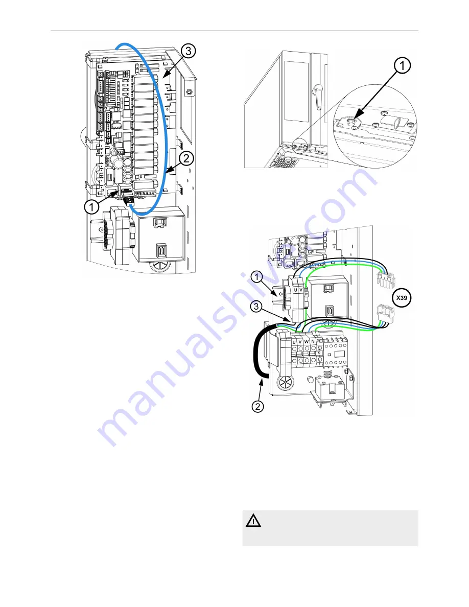
remove the left side cover of the appliance.
loosen the control panel by unscrewing the m4 bolt with washer
(1) from underneath the control panel (see fig. 18), and remove the
panel by sliding upwards, pull out towards you and flip out to the left.
figure 18: loosening the control panel
attach the fuse holders and terminal from the hood set to the diN
rail (1) at the front of the electrical board (see fig. 19)
figure 19: Connecting the 623 hood set
insert connector X39 from the hood set into plug X39, which leads
from the main terminal block of the appliance.
in the base of the appliance, break through the flange marked
with the number “1” (see fig. 15), insert cable gland pg 13,5
(which is a component of the hood) into the gland and thread the
hood’s power cable through it into the appliance.
Connect the individual wires of the hood’s power cable (2) from
below (3) to the fuse holders and to terminals pE from the hood set
(see fig. 19).
do not confuse with the fuse holders on the main terminal block
of the appliance!
Technical documentation I Vision Vent 2 Hood I Transport and installation


