background image


Operating the Device 


64 


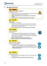
NOTICE


N15.0000


Damage to the grinding jars 

Incorrect filling of the grinding jars 

  The grinding balls damage the grinding jar and the device if the grinding 

jars are not filled with any material or with insufficient material. 


Do not operate the device without material in the grinding jars.


The filling in the grinding jars must not be less than 25 % of the 
grinding jar volume.


6.12  Changing the grinding jar seal for cryogenic grinding  


In terms of cryogenic grinding, depending on the selected temperature range, it may be 
necessary to replace the grinding jar seal, since this is the only way to ensure that the grinding 
jars remain tight even during considerable cooling. 
For this purpose, white Teflon (PTFE) seals are supplied with the MM 500 control, which are 
suitable for low temperatures up to -200 °C.  


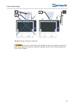
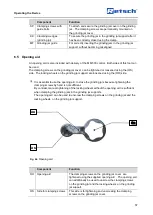
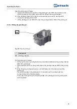
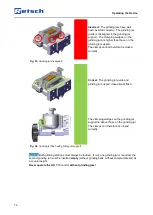
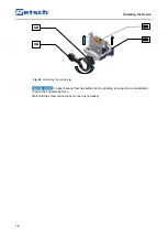
Fig. 45: 

Replacing the grinding jar seal for cryogenic grinding 


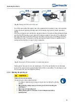
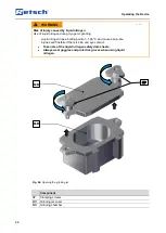
In order to replace the seal, please proceed as follows: The grinding jar seal is embedded in an 
elliptical groove with a notch around its circumference. Dismantle the black sealing ring using a 
screwdriver (1). In order to do this, insert the screwdriver into the notch so that the grinding jar 
seal can be levered out (2). Be careful not to damage the seal. If necessary, refrain from using 
the seal again.  
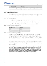
Take a white PTFE sealing ring from the scope of delivery of the MM 500 control and carefully 
press it together so that it takes on the shape of the groove for the sealing ring (3). Avoid 
bending the sealing ring. Then insert the ring into the groove for the sealing ring and press it as 
far as possible into the groove for the sealing ring.  
 

Summary of Contents for Mixer Mill MM 500 control

Page 1: ... Retsch GmbH 42781 Haan Retsch Allee 1 5 Germany 31 08 2021 Version 0001 Manual Mixer Mill MM 500 control Translation ...

Page 2: ...2 Copyright Copyright by Retsch GmbH Retsch Allee 1 5 42781 Haan Germany ...

Page 3: ... cooling system 24 3 4 Connection of MM 500 control to external cooling systems 25 3 4 1 Operating the MM 500 control with the cryoPad 26 3 4 2 System overview MM 500 control and cryoPad 27 3 4 3 Operating the MM 500 control on a chiller e g the Lauda Microcool MC 1200 28 3 4 4 System overview MM 500 control and Lauda Microcool MC 1200 30 3 4 5 Operating the MM 500 control with a cryostat 31 3 4 6...

Page 4: ...nding with the optional cryokit 62 6 10 Wet grinding 63 6 10 1 Wet Grinding with Highly Flammable Materials 63 6 11 Preparing the grinding jar 63 6 12 Changing the grinding jar seal for cryogenic grinding 64 6 12 1 Opening the grinding jar 65 6 12 2 Filling the grinding jar 67 6 12 3 Closing the grinding jar 68 6 13 Inserting the Grinding Jar 69 6 13 1 Opening the grinding jar support 70 6 13 2 In...

Page 5: ...on 108 7 13 8 Operating Hours 108 7 13 9 Serial number 108 7 13 10 Software Update 108 7 13 11 Service Environment 108 8 Error Messages and Information Notes 110 8 1 Error Messages 110 8 2 Information Notes 115 9 Servicing 118 9 1 Cleaning 118 9 1 1 Cleaning the outside of the device 119 9 1 2 Cleaning the collecting tray 119 9 1 3 Cleaning the inside 119 9 1 4 Cleaning the grinding jar 119 9 1 5 ...

Page 6: ...Notes on the manual 6 ...

Page 7: ...manual has been prepared in accordance with the Machinery Directive 2006 42 EC 1 1 Disclaimer This manual has been prepared with great care We reserve the right to make technical changes We assume no liability for personal injuries resulting from the failure to follow the safety information and warnings in this manual No liability will be assumed for damage to property resulting from the failure t...

Page 8: ...n is disregarded There is an increased risk of a serious accident or of a possibly fatal personal injury The signal word WARNING is additionally used in the running text or in instructions CAUTION C1 0000 Risk of injuries Source of danger Possible consequences if the danger is ignored Instructions and information on how to avoid the risk Average to slight injuries may result if the Caution sign is...

Page 9: ... device The MM 500 control is designed for the crushing grinding mixing and homogenisation of wet and dry soft medium hard fibrous and brittle materials with a particle size of up to 10 mm As a laboratory machine the MM 500 control may only be used to prepare samples and not as a production machine The device has been designed for stationary use in a dry and clean working environment The user and ...

Page 10: ... PPE Ensure that the following conditions have been met Staff have read and understood this Manual and in particular the chapter on Safety Staff are aware and take note of the relevant accident prevention and safety regulations Staff wear the designated personal protective equipment PPE when working with the device 2 3 3 Workstation and device Ensure that there is sufficient lighting and ventilati...

Page 11: ... an emergency stop switch as standard In an emergency it must be shut down by pressing the main button or by disconnecting the device from the power supply Hood lock The MM 500 control is equipped with an automatic hood lock Once a grinding process has started a magnetic clamp firmly closes the hood of the device If the hood is nevertheless opened during a grinding process the process is interrupt...

Page 12: ...technical application limits During operation do not wear any jewellery wear your hair down or wear a tie or similar loose item of clothing Wearing hearing protection during operation Before operating the device take measures that take account of restricted communication during operation of the device Pay attention to your surroundings during grinding because the noise makes it more difficult to p...

Page 13: ...the grinding jar and then close the jar The high pressure that arises in the jar would burst the grinding jar open Only clean the device with a dry or damp cloth Do not use any solvent or aggressive detergent for cleaning Only use original spare parts for maintenance work 2 8 Confirmation Form for the Managing Operator This manual contains essential instructions for operating and maintaining the d...

Page 14: ...e I have read and taken note of the contents of all chapters in this manual as well as all safety instructions and warnings User Surname first name block letters Position in the company Place date and signature Managing operator or service technician Surname first name block letters Position in the company Place date and signature ...

Page 15: ...ars are cooled indirectly from the bottom The temperature of the thermal plates can be read on the display The device enables fast grinding mixing and homogenization of soft medium hard hard hard brittle and fibrous materials up to a particle size of 10 mm Due to the effective grinding process in a closed system the MM 500 control ensures a gentle sample preparation which is ready for analysis in ...

Page 16: ...ssure generator Autofill LN2 150 l 2 MM 500 control Set Liquid thermal fluid The set consists of Vibration mill MM 500 control Hose set for the connection to a chiller Chiller is not included in the set 3 MM 500 control Vibration mill MM 500 control This laboratory device is designed for 8 hour single shift operation at 30 duty cycle PLEASE NOTE This unit must not be used as a production machine o...

Page 17: ...g time Digital 10 seconds minimum to 8 hours maximum Adjustable cooling time 1 to 60 min only with accessory device cryoPad Article number 70 950 0001 Maximum grinding time Up to 99 hours Number of grinding stations 2 Grinding jar sizes 50 ml 80 ml 125 ml Grinding jars Materials hardened steel stainless steel tungsten carbide zirconium oxide Sensors Temperature pressure optional Operation 4 3 inch...

Page 18: ... unit chiller cryostat via hose set Art No 02 707 0188 Connection thread hose set External thread G1 4 External thread G 3 8 Is the operation as an open system possible Yes Is the operation as a closed system possible Yes Materials in contact with liquid material incompatibilities Stainless steel 1 4305 Stainless steel 1 4301 Steel galvanized Nickel plated brass Thermal specifications Can the grin...

Page 19: ...e working environment Where necessary use additional visual signals CAUTION C3 0077 Risk of hearing loss High sound level The sound level may be high depending on the type of material the number of balls used the set grinding frequency and the grinding time Excess noise in terms of intensity and duration can lead to impairments or permanent damage to hearing Ensure you take suitable soundproofing ...

Page 20: ...et hose bursting The maximum pressure in the external liquid nitrogen supply line may be a maximum of 1 5 bar The use of a safety valve is absolutely essential The connection for the liquid nitrogen LN2 is a G 1 4 inch threaded connector The operating pressure in the liquid nitrogen supply line should be at least 0 5 bar The lower the pressure of the liquid nitrogen supply line the longer the prec...

Page 21: ...ICE Depending on the ambient temperature air humidity and duration of use small quantities of water may drip from the collecting filter 3 3 Views of the device 3 3 1 Front Fig 3 Device cover closed Fig 4 Device cover open H T AS MS HM HM ...

Page 22: ...Holding the grinding jars SR Locking wheel To tighten or loosen the grinding jars in the grinding jar support KK Clamping wedges Grinding jar support Fasten the grinding jar after it has been correctly locked with the clamp KS Direction of rotation of the locking wheel Close clamp Closes the clamp and thereby fastens the grinding jar in the grinding jar support MF Grinding jar guide For correct in...

Page 23: ...e of both temperatures is displayed MB Grinding jar For holding the sample material to be ground and the grinding balls Insert the grinding jar into the grinding jar support and make sure that the bottom of the grinding jar rests on the thermal plate in order to ensure optimum cooling The thermal plate cools the grinding jar via the grinding jar bottom In order to ensure that the grinding jar and ...

Page 24: ...fan To conduct the waste heat RB Retschbox Optionally available device Among other things it enables remote device control AK Connections for the cooling system Connections for the cooling system e g the cryoPad SC Interface for the cryoPad Interface for the communication with the cryoPad The MM 500 control can be operated with a number of cooling options 3 3 5 Changing the connections for the coo...

Page 25: ...g system from the left side CAUTION The operation from both sides at the same time is not possible 3 4 Connection of MM 500 control to external cooling systems CAUTION If the MM 500 control was connected to an external cooling unit using a liquid medium e g water as coolant the piping system of the mill must be carefully drained with compressed air before changing to a cooling system with liquid n...

Page 26: ...jury in the event of an uncontrolled escape of liquid nitrogen Stop the liquid nitrogen supply line immediately 3 4 1 Operating the MM 500 control with the cryoPad The MM 500 control offers the possibility to connect the cryoPad as an optional additional device for supplying liquid nitrogen With the cryoPad the supply of liquid nitrogen is clocked in such a way that temperatures in the thermal pla...

Page 27: ...o the inflow and return ducts of the two thermal plates via four connections By selectively cycling the nitrogen flow the cryoPad enables the temperatures of the right and left thermal plate of the MM 500 control to be controlled within narrow temperature limits In this regard the cryoPad takes over the exact control with the help of a PID controller and enables the parameter temperature to be kep...

Page 28: ...ydraulic circuit the system can be operated more ecologically than at the water tap If both thermal plates shall be cooled with the chiller the connection e g to the Lauda Microcool MC 1200 is as follows Fig 13 Rear side of the device with the Lauda Microcool MC 1200 using both thermal plates If only one thermal plate shall be cooled the chiller can be connected either to the upper connections rig...

Page 29: ...h the Lauda Microcool MC 1200 use of individual thermal plates The MM 500 control can be optionally connected with a pre assembled hose assembly Art No 02 707 0188 The complete connection is shown below Fig 15 The pre assembled hose assembly Return Inflow Return Inflow ...

Page 30: ...he heat exchanger and the liquid lines The temperature control medium leaves the chiller at the flow connection The volume flow is divided by Y connectors and directed to the two thermal plates of the MM 500 control The rotary transmissions enable the transport of the temperature control medium to the thermal plates in the vibrating grinding jar supports The cooling capacity or heating capacity of...

Page 31: ...ve temperature range It must be taken into account that when using a cryostat a sufficient control reserve must always be kept available In other words the possible flow temperature must always be lower than the temperature to be maintained at the thermal plates or the sample The MM 500 control was tested with devices from the company Huber GmbH which generate a flow temperature of 85 C In order t...

Page 32: ... is carried out as follows Fig 18 Rear side of the device with cryostat The MM 500 control can be optionally connected with a pre assembled hose assembly Art No 02 707 0188 The complete connection is shown below Fig 19 The pre assembled hose assembly Return Inflow ...

Page 33: ...changer and the liquid lines The temperature control medium leaves the cryostat at the flow connection The volume flow is divided by Y connectors and directed to the two thermal plates of the MM 500 control The rotary transmissions enable the transport of the temperature control medium to the thermal plates in the vibrating grinding jar supports The cooling capacity or heating capacity of the temp...

Page 34: ...Thus lower temperatures at the cold plates can be achieved 3 5 Signs on the device Fig 22 Instructions on the front side of the device No Instructions Meaning W1 Wear protective gloves Safety Instructions Wear protective gloves to prevent any injuries from heat or cold W2 Hot surface Safety notice The surface of the thermal plates or the grinding jars may heat up during operation W3 Wear safety go...

Page 35: ... period of time B Read operating instructions carefully Safety notice The operating instructions of the device must be read carefully before commissioning and operation L Power warning Caution Beware of electric shock The housing of the device may only be opened by trained personnel Pull out the power plug before performing any maintenance work N Type plate Information Performance and connection d...

Page 36: ...ial number 5 Manufacturer s address 6 CE mark 7 Disposal sign 8 Barcode 9 Power version 10 Mains frequency 11 Power 12 Current 13 Number of fuses 14 Fuse type and fuse rating Please always specify the device name 1 or article number 3 as well as the serial number 4 of the device if you have any questions 1 2 3 4 5 6 7 8 9 10 11 12 14 13 ...

Page 37: ...e packaging guidelines NOTICE N2 0001 Complaint or return Keeping the packaging Inadequate packaging and insufficient securing of the device can jeopardise the warranty claim in the event of a complaint or return Keep the packaging for the duration of the warranty period 4 3 Transport WARNING W3 0005 Risk of injury due to the device falling down Lifting the device above head height The device can ...

Page 38: ...016 Damaged components due to condensation Temperature fluctuations The device may be exposed to substantial fluctuations in temperature during transport The ensuing condensation can damage electronic components Wait until the device has acclimatised before putting it into service Temporary storage Also in case of an interim storage the device must be stored dry and within the specified ambient te...

Page 39: ...40 C ambient temperature of the device The MM 500 control sets special requirements in terms of the installation site Please note that the device must be set up on a solid and firm surface The surface should be able to carry a load of 90 kg without any concerns and be horizontal on all sides without any inclination Please be aware that the device must be lifted by at least two people when it is se...

Page 40: ...rature Max rel humidity 31 C 80 33 C 73 3 35 C 66 7 37 C 60 39 C 53 3 40 C 50 NOTICE N9 0015 Humidity High relative humidity Electronic and mechanical components may be damaged The performance data alter to an unknown extent The relative humidity in the vicinity of the device should be kept as low as possible Installation height max 2 000 m above sea level The MM 500 control must be set up on a so...

Page 41: ... exhaust gas flow Do not place any electronic devices in the immediate vicinity In case that the base is not sufficiently waterproof please contact Retsch GmbH for any suitable accessories Fig 26 Material damage caused by condensation CAUTION Use the machine only on resistant surfaces because the surfaces may become damaged from the usage of coolants 4 6 Remove packaging Remove the eight screws se...

Page 42: ...aging crate upwards Fig 28 Lifting off the packaging crate 4 7 Removing the Transportation Lock WARNING W5 0005 Risk of injury due to the device falling down Lifting the device above head height The device can fall causing serious injuries when lifted above head height Never lift the device above head height ...

Page 43: ...rt lock Component S Screw TS Transport lock Remove the transport lock and transport the device as described below Loosen and remove the six screws S There are three on each side of the device The transport lock can also be used as a transport aid Use the transport lock TS as a transport aid and transport the device to the place of use CAUTION The weight is approx 62 kg without the grinding jars Th...

Page 44: ...faces Grasp the transport aid as shown Reach through the handle holes to lift Do not reach underneath the transport aid The transport aids have been statically and dynamically tested up to a machine weight of 150 kg Avoid repeated bending of the handles back and forth Before lifting please make sure that the safety latch is closed and locked in place TH ...

Page 45: ...ft the device with a crane Transport the device with a crane as follows Attach the lifting straps to the two transport aids TH Transport the device to the place of use by crane PLEASE NOTE If the lifting straps are too short the housing may become damaged The four lifting straps must be long enough to ensure a minimum distance of 100 cm between the device and the lifting device TH TH ...

Page 46: ...ing element Press the safety latch down with your thumb in order to release the latching element and then move the safety latch to the right counterclockwise in order to release the latch Fig 34 Opening the safety latch SR Remove the transport aids as follows Push the transport aid to the right Fig 2 point 1 Pull it out and remove the transport aids Fig 2 point 2 SR SR ...

Page 47: ...stallation 47 Fig 35 Removing the transport aid Component TH Transport aid The procedure for removing the transport aid on the left side works analogously Keep the transport aids for any transport of the device in the future TH ...

Page 48: ...nent TH Transport aid Insert the transport aids as follows Align the transport aid on the two screws Fig 1 by moving it back and forth Fig 2 Push the transport aid in as far as it will go Fig 3 Push the transport aid to the left until it audibly clicks into place Fig 4 PLEASE NOTE Close the safety latch TH TH TH ...

Page 49: ...re to observe the values on the type plate Electronic and mechanical components may be damaged Connect the device only to a mains supply matching the values on the type plate WARNING When connecting the power cable to the mains supply use an external fuse that complies with the regulations applicable to the place of installation Check the type plate for details on the necessary voltage frequency a...

Page 50: ...e to the power supply as described below Match the specified voltage and frequency on the type plate N of the device with the values on site Plug the enclosed mains lead into the appliance socket M Plug the other end of the mains lead into a socket at the installation site Provide external fuse protection in accordance with the regulations of the installation site M N ...

Page 51: ...ctronic components WARNING When using a cryoPad please note the following Under no circumstances should power cables power supply units or electronic devices be positioned near the outlet for the liquid nitrogen A There is a risk of damage NT A NT A ...

Page 52: ...N C11 0077 Risk of hearing loss High sound level The sound level may be high depending on the type of material the number of balls used the set grinding frequency and the grinding time Excess noise in terms of intensity and duration can lead to impairments or permanent damage to hearing Ensure you take suitable soundproofing measures Wear hearing protection if there is loud or lasting noise CAUTIO...

Page 53: ...Operating the Device 53 6 1 Switching the device on off Fig 39 Main switch Fig 40 Front side of the device with touch display Component I Main switch H Device cover T Touch display with dial T I H ...

Page 54: ...eady for operation Switch off the device as follows Turn off the device with the main switch I on the rear side of the device if no grinding process is running 6 2 Opening and Closing of the Device CAUTION C14 0008 Risk of pinching and bruising Device hood closing The device hood can trap fingers when closing thereby causing pinching or bruising Never allow the device hood to close by itself Alway...

Page 55: ... H down by hand and close it completely The device hood is fitted with cushioning which ensures that the device hood does not close in an uncontrolled manner The cushioning on the device hood takes effect as from an opening angle of 80 6 3 Specifications regarding grinding balls and grinding jars NOTICE N12 0011 Wear or damage to the grinding balls and grinding jars Use of different materials Grea...

Page 56: ...terial of the grinding jar PLEASE NOTE For grinding that reaches temperatures below 0 C grinding sets made of steel should preferably be used CAUTION If you use grinding jars made of other materials for cryogenic applications they must never become colder than 100 C CAUTION Damage due to imbalance Both grinding stations in the machine must always be loaded When grinding only one sample an empty gr...

Page 57: ...ing wheels on the grinding jar support are loosened using the ÖR side It is essential to use the opening aid to close the grinding jars because tightening the clamping screws by hand is not sufficient By contrast manual tightening of the locking wheels without the opening aid is sufficient when clamping the grinding jars in the grinding jar supports The opening aid can be used to unscrew the clamp...

Page 58: ...ixer Mill When grinding bulk materials a grinding jar filling should consist roughly of one third sample material and one third ball volume The remaining third is the empty grinding jar volume that the balls need in order to move Please pay attention to the maximum permitted ball size for the material in question If an increase in volume or decrease in volume is to be expected during grinding the ...

Page 59: ...osphere are not toxic However a change in concentration in particular changes to the oxygen concentration may have effects on life and burns It is therefore essential for the air breathed in to contain sufficient oxygen 19 Humans cannot detect changes in the composition of air within the time that will actually be necessary because the components are colourless and odourless 6 7 1 Dangers A danger...

Page 60: ...n metre Only trained personnel may work with liquid nitrogen This list is not complete 6 7 4 General conduct in the case of an accident In the case of an accident from oxygen deficiency the following regulations should be observed Secure the surrounding area to avoid any subsequent accidents Act quickly The rescuers must take measures to protect themselves respiratory protection device Move the in...

Page 61: ...el Wear personal protective equipment suitable gloves goggles or face protection and safety shoes Keep the vessel upright Use suitable material e g metal hose or PTFE hose to refill Train personnel This list is not complete 6 8 4 General rules of conduct for splashes with liquid nitrogen 6 8 4 1 To the eyes Rinse eyes with much water for 15 min Follow the company instructions for emergencies Consu...

Page 62: ... of for instance thermoplastics rubber products fatty foods pharmaceuticals etc For cold grinding the MM 500 control offers a cryokit order number 22 354 0003 for cooling the grinding jars with liquid nitrogen Perform a pre embrittlement of elastic and tough sample material as follows Pre embrittlement of sample material for grinding must be done indirectly Use only grinding balls and grinding jar...

Page 63: ...nuously present It must therefore be prevented that explosive vapors escape from the clamped grinding jars during the grinding process or may be able to reach areas where the necessary ignition energy is present In particular these vapors are also pressed outwards by the heating that takes place and the resulting increase in pressure inside the grinding jar It is therefore urgently recommended tha...

Page 64: ... white Teflon PTFE seals are supplied with the MM 500 control which are suitable for low temperatures up to 200 C Fig 45 Replacing the grinding jar seal for cryogenic grinding In order to replace the seal please proceed as follows The grinding jar seal is embedded in an elliptical groove with a notch around its circumference Dismantle the black sealing ring using a screwdriver 1 In order to do thi...

Page 65: ...sary use the opening aid provided If there is resistance when turning both star handles the seal is fully compressed Fig 47 Checking the PTFE seal whether it is mechanically secured Subsequently the cover can be unscrewed again Check the seal whether it is mechanically secured The seal should be approximately flush with the cover surface The grinding jar cover is then ready to be used for cryogeni...

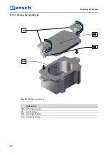
Page 66: ...ogen has a boiling point of 196 C and causes burn like injuries and frostbite if there is skin and eye contact Take note of the liquid nitrogen safety data sheets Always wear goggles and protective gloves when using liquid nitrogen Fig 48 Opening the grinding jar Component SP Clamping screws MD Grinding jar cover MR Grinding chamber MD SP MR ...

Page 67: ...49 Filling the grinding jar Component MR Grinding chamber Fill the grinding jar as follows Fill the right number of grinding balls made of a suitable material into the grinding chamber MR of the grinding jar Add material for grinding to the grinding balls in the grinding chamber MR of the grinding jar When filling the grinding jar take care not to fall below 1 4 of the total volume of the grinding...

Page 68: ...Operating the Device 68 6 12 3 Closing the grinding jar Fig 50 Closing the grinding jar Component MD Grinding jar cover FB Guide bolts MR Grinding chamber SP Clamping screws SP MD MR FB ...

Page 69: ... case leave the second grinding jar empty no grinding balls no sample material Switch the device off immediately if it is vibrating strongly and making a loud noise and check the number the gross weight and correct position of the grinding jars NOTICE N17 0011 Wear or damage to the grinding balls and grinding jars Use of different materials Greater wear or damage is possible when operating the dev...

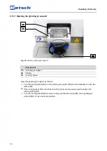
Page 70: ... the grinding jar support as follows Turn the locking wheel SR on the grinding jar support MH counterclockwise to open the clamp KB If the locking wheel SR cannot be turned by hand use the opening aid to loosen the locking wheel SR Turn the locking wheel SR as far as it will go so that the clamp KB of the grinding jar support MH is open as far as possible MH SR KB ...

Page 71: ...ectly positioned in the grinding jar support and must not become misaligned when inserted The edges of the grinding jar guide MF and of the grinding jar support MH must close almost flush NOTICE The grinding jars must be correctly inserted in the grinding jar support and be clamped firmly using the clamp To this end the grinding jar must be pushed as far as possible into the grinding jar support w...

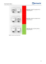
Page 72: ...ned Correct The grinding jar guide and grinding jar support close almost flush The clamping wedges on the grinding jar support lie above those on the grinding jar The clamps can therefore be closed correctly Fig 54 Grinding jar flush with grinding jar support NOTICE Both grinding stations must always be loaded If only one grinding jar is required the second grinding jar must be inserted empty with...

Page 73: ... 73 Incorrectly loading the grinding stations with grinding jars Incorrectly loading the grinding stations with grinding jars Correctly loading the grinding stations with grinding jars Fig 55 Loading the grinding stations ...

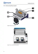
Page 74: ...Operating the Device 74 6 13 3 Closing the grinding jar support Fig 56 Clamping the grinding jar Fig 57 Device with loaded grinding stations SR MH KB MB KK ...

Page 75: ...afety data sheets for the sample material CAUTION C17 0006 Risk of injury Sample material that is harmful to health Sample material that is harmful to health can injure people illness contamination Use suitable extraction systems with sample material that is harmful to health Use suitable personal protective equipment with sample material that is harmful to health Take note of the safety data shee...

Page 76: ... the grinding process Component H Device hood T Touchscreen DK Dial Start the grinding process as follows Close the device hood H by hand Configure the parameters for grinding on the touchscreen T and using the dial DK Press on the touchscreen T to start the grinding process The grinding process can only be started by pressing if this symbol is displayed on the touchscreen If is not displayed on t...

Page 77: ...when handling the grinding jar Never open hot grinding jars Allow grinding jars to cool down to room temperature before opening them NOTICE N19 0007 Handling foodstuffs pharmaceuticals and cosmetic products Products processed Foodstuffs pharmaceuticals and cosmetic products that have been processed on the device may no longer be eaten used or put into circulation Dispose of these substances accord...

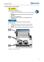
Page 78: ...78 Fig 60 Removing the grinding jar PLEASE NOTE In case that any frost has settled on the grinding jar supports do not attempt to open the supports by force Wait until the screw connections can be opened easily SR ÖH MH MB ...

Page 79: ... cover SR Star handles MH Grinding jar support ÖH Opening aid MB Grinding jar SP Clamping screws MD Grinding jar cover MR Grinding chamber If the star grips SR are heavily iced do not attempt to open the grinding jar by force Wait until the screw connections can be opened easily MD SR MR ...

Page 80: ...he grinding jar support MH by hand or if necessary with the matching side of the opening aid ÖH Remove the grinding jar MB by pulling it upwards out of the grinding jar support MH Open the clamping screws SP of the grinding jars MB with the matching side of the opening aid ÖH Lift off the grinding jar cover MD Remove the sample material from the grinding chamber MR ...

Page 81: ...curring grinding processes are configured stored and selected as necessary in the program and cycle mode The system settings for the MM 500 control are also selected from the main menu and can be changed where necessary Fig 62 Touchscreen and dial Control element Function T Touchscreen Touchscreen for selecting the function elements DK Dial To configure the parameters for the grinding process the ...

Page 82: ...Device control 82 7 3 Menu interface on the touchscreen The menu surface of the touch display is divided into the following areas Fig 63 Menu surface of the touch display B N P S ...

Page 83: ...bration frequency Remaining grinding time Total duration and progress of the cycle program Actual temperature only when using a cryoPad Remaining cooling time only when using a cryoPad B Scroll bar Indicator for the position of the menu S Control The device is controlled directly with the functional elements in this area Start pause and cancel the grinding process Select edit save delete and start...

Page 84: ... cover appears on the touch display By opening and closing the device cover once the device is ready for operation Close device cover System settings This calls up the system settings Program mode Access to the Program mode Gallery view Call up gallery view The stored programs are displayed and can be selected directly Vibration frequency Vibration frequency for configuration of the grinding proce...

Page 85: ...le program This saves a created program or a cycle program Cancel Cancel input return to previous menu Start This starts the grinding process Pause This pause the grinding process Continue This continues the grinding process after being paused Stop This stops the grinding process Temperature This defines the target temperature Only with cryoPad connected Cooling off This switches off the cooling O...

Page 86: ...Device control 86 Brightness Calendar Software version Operating time QR code Update Maintenance Cycle program Total operating time Sound on ...

Page 87: ...by the main switch Touchscreen is activated and the dial lights up in blue Prompt to open and close the device hood is displayed on the touchscreen Open and close the device hood Device is ready to use Main menu System settings Program mode Cycle mode Start the grinding process Stop Pause Con tinue ...

Page 88: ... via the Main menu Parameters for the grinding process can be configured and the grinding can also be started Fig 65 Main menu after being switched on with closed cover Fig 66 Menu view before starting the grinding process N1 1 N2 1 N3 1 P1 1 P2 1 B S1 1 S3 1 P1 1 P2 2 N4 ...

Page 89: ...ng grinding time of the current grinding process P3 1 Temperature The MM 500 control shows the current temperature of the thermal plates during the grinding B Scroll bar Indicator for the position of the menu S1 1 Close device cover Before starting a grinding process the device cover must be opened once to insert the grinding jars If the device cover is then closed again the indicated element disa...

Page 90: ...cally once a defined grinding time has expired Grinding can also be actively stopped by pressing the stop button Press to stop the grinding 7 11 Program mode Press the button N2 1 in the Main menu to switch to the Program mode The display changes to the current program Individual programs can be selected edited saved deleted and started in the Program mode If sample materials are frequently ground...

Page 91: ...ding via a program the grinding parameters cannot be changed during the grinding process Fig 68 Program mode Fig 69 Program mode after starting the grinding process P1N B N3 2 S3 1 N1 2 P1 1 N1 3 S2 1 S3 2 P2 1 S4 S2 2 P1N P2 2 S4 P1 1 P3 1 ...

Page 92: ...ed P2 2 Remaining grinding time Displays the remaining grinding time of the current grinding process P3 1 Temperature The MM 500 control shows the current temperature of the thermal plates during the grinding B Scroll bar Indicator for the position of the menu S2 1 Pause grinding process Stops the grinding process Pressing it again continues the grinding process S2 2 Editor mode Opens the Editor p...

Page 93: ... You can change the program by swiping to the right or left on the touch display The scroll bar B gives you a visual overview of your position within the individual programs Fig 71 Program view P1N B N3 2 S3 1 N1 2 P1 1 P2 1 S4 S2 2 B N3 2 ...

Page 94: ...llery view of the programs or the available program memory locations N4 Acoustic signals on off The sound is switched on when the element is visible P1N Program number Number of the selected program P1 1 Vibration frequency After selection with the touch display the vibration frequency can be set from 3 30 Hz with the dial P2 1 Grinding time After selection with the touch display the grinding time...

Page 95: ... S1 2 Delete Deletes all parameters of the program S2 3 Save Saves the program Editing can be cancelled by pressing the button N2 2 All settings made will then be discarded Changing the program Press on the parameter which needs to be edited Turn the rotary knob until the requested value is displayed Press the parameter again or select another parameter in order that the set value is accepted Dele...

Page 96: ...lected edited saved deleted and started If sample materials are frequently ground with the same parameters these parameters can be stored in cycle program memory locations and called up as Standard Operating Procedures SOP whenever required Up to four memory locations are available for cycle programs The following parameters can be stored in the individual cycle programs Vibration frequency Grindi...

Page 97: ...Device control 97 Fig 74 Cycle program mode Fig 75 Cycle program mode after starting the grinding process N1 2 B S2 2 S3 1 ZN PE PS DZ WZ S2 1 S3 2 ZN PE PS DZ WZA AT ...

Page 98: ...ed here B Scroll bar Indicator for the position of the cycle program DZ Total duration of the cycle program Shows the total duration of the cycle program until the grinding process is completed The total duration is made up of the two parameter sets A B and the repetitions The total duration of a cycle program is limited to 99 hours S2 1 Pause cycle program Pauses the current cycle program S2 2 Ed...

Page 99: ...otal duration of the cycle program until the grinding process is completed The total duration is made up of the two parameter sets A B and the repetitions The total duration of a cycle program is limited to 99 hours S2 2 Editor mode Opens the editor of the cycle program S3 1 Start cycle program Starts the grinding process or the cycle program Swipe the display from right to left or from left to ri...

Page 100: ...Device control 100 Fig 77 Editor of the cycle program when using a cryoPad Fig 78 Editor of the cycle program when using a chiller N1 2 N2 2 S1 2 GS6 PE DZ N1 2 N2 2 S1 2 GS6 PE DZ ...

Page 101: ...9 hours A total duration of more than 99 hours cannot be saved and is marked in red The process can be cancelled by pressing the button All settings made will then be discarded The parameters can only be changed In the Cycle program mode if editing is activated via the button Press the parameter which needs to be edited Turn the rotary knob until the required value is displayed Press the parameter...

Page 102: ...Device control 102 Fig 79 System settings Page 1 Fig 80 System settings Page 2 SE1 SE2 SE3 SE5 SE6 SE4 ...

Page 103: ...re drift Setting of the maximum permissible temperature deviation of the left and right thermal plate Disabled by default See comments on Note H46 SE5 Brightness Adjusting the display brightness SE6 Date and time Setting of date and time SE7 Software version Display of software version Display program control Firmware device control The software version of the cryoPad is displayed Only when cryoPa...

Page 104: ...via a smartphone with the appropriate software and an Internet connection Additional information such as tips and tricks and an application database can then be accessed Tap on the myRetsch section to display the QR code Fig 82 myRetsch QR code for accessing the web portal Fig 83 QR code MM 500 control myRetsch https retsch info g20767 ...

Page 105: ... control is only possible after the optional Retschbox WLAN module has been installed and set up After a connection to the device has been established via remote the device is controlled exclusively with the corresponding smartphone tablet or PC On the device itself it is only possible to select in order to cancel the grinding process All the other functional elements on the touch display are inac...

Page 106: ... permissible temperature difference can be set in 5 C steps between 5 C and 50 C In the factory default setting this option is switched off OFF The MM 500 control offers the option to measure the temperature of the right and left thermal plate and thus to provide a comparison between those temperatures If the load is balanced including grinding jar volume sample and number of balls an approximatel...

Page 107: ...re drift 7 13 5 Brightness Proceed as follows to adjust the brightness level on the touchscreen Press the section Turn the dial until the desired level of brightness has been reached on the display The set value will be accepted as soon as you press this section again or on another section or as soon as you exit system settings ...

Page 108: ...g a grinding process The time cannot be manipulated 7 13 9 Serial number The serial number of the device can be displayed in this section 7 13 10 Software Update The software can be updated using this section There must be a suitable USB data carrier in the USB interface The USB data carrier must be formatted to the FAT32 file system USB 3 0 data carriers are not supported Only the software to be ...

Page 109: ...vated and On displayed beneath the symbol No other functions will be executed however Deactivate the service environment by pressing on the section or exit the System settings menu by pressing the button All other functions remain deactivated while the service environment is activated ...

Page 110: ...high frequency Check whether the load of the machine is too high Check whether there are any foreign bodies present in the interior Check whether the arms can be moved easily by hand Check whether the grinding process can be carried out with reduced frequency Leave the machine switched on until the Cool Down Timer has expired E20 Error Control Turn off the main switch and wait 30 sec before turnin...

Page 111: ...ke sure that the cassette is not overfilled If the error persists please contact the service of MM 500 control E26 Error Frequency converter The communication with the frequency converter is interrupted or faulty Turn off the main switch and wait 30 sec before switching the device on again If the error persists please contact the service of MM 500 control E41 Error Speed sensor The set rotation sp...

Page 112: ...tching the device on again If necessary remove any foreign objects from the interior of the device If the error persists please contact the service of MM 500 control E80 Error USB interface An update was carried out via the Settings menu No USB stick is connected or the USB stick does not contain any information Turn off the main switch and wait 30 sec before switching the device on again If the e...

Page 113: ... beginning of the cooling process the MM 500 control carries out a safety check to determine whether the connecting lines between the cryoPad and the MM 500 control are connected The machine checks whether the sensors inside the device cool down as expected and whether operation is as intended Check whether the connection lines between the cryoPad and the MM 500 control are tightly connected and d...

Page 114: ...o the specification in the Technical Data Check whether the connection lines between the cryoPad and the MM 500 control are tightly connected and do not leak Check and ensure that no significant leakage of nitrogen is visible A nitrogen leakage can be recognized by nitrogen drops beading on the table surface until they have evaporated Check whether ambient conditions for room temperature and humid...

Page 115: ...ogramme processes The operation of the device or programme may be interrupted briefly but there is no fault The information notice must be acknowledged by the user to continue the process Information notices provide additional information for the user as an aid but do not represent any device or programme errors ...

Page 116: ...cy Leave the machine switched on until the Cool Down Timer has expired H42 Safety check after commissioning the device Open the device cover and close it again H46 Temperature drift The temperature difference set by the user has been exceeded Check whether the set temperature difference is reasonable for your grinding process Please keep in mind that unequal loads grinding jar volume number of bal...

Page 117: ...erature as well as the actual temperature is displayed underneath the information symbol As soon as the machine has warmed up the start screen is released again The user can start the grinding process Wait until the machine has warmed up sufficiently The notice will automatically disappear as soon as the displayed temperature values have sufficiently approached You can then start the process In or...

Page 118: ... injuries caused by an electric shock if the device has not been disconnected from the power supply Only carry out cleaning work on the device when it has been disconnected from the power supply Use a cloth moistened with water for cleaning Do not clean the device under running water WARNING W14 0008 Risk of death caused by an electric shock Penetration of water if the mains plug is not fully plug...

Page 119: ...or detergent gets inside the device 9 1 4 Cleaning the grinding jar All grinding jars including those with glued in ceramic inserts can be cleaned using alcohol benzine or normal household detergent Cleaning in a dishwasher is also possible After cleaning the grinding jars can be dried in the drying cabinet at the following temperatures Grinding jar material Temperature Hardened steel Up to 200 C ...

Page 120: ...ld be regularly checked for wear and replaced if necessary Likewise all existing sealing gaskets of grinding tools and in the device should be checked for wear regularly and replaced if necessary 10 1 Returning for repair and maintenance Fig 88 Return form The acceptance of devices and accessories of the Retsch GmbH for repair maintenance or calibration can only be effected if the return form incl...

Page 121: ...com website under the Downloads section for the device Information about parts subject to wear and tear and small accessories can be found in the complete catalogue for the Retsch GmbH likewise available on the website In the event of questions about spare parts please contact the representative for Retsch GmbH in your country or contact Retsch GmbH directly ...

Page 122: ...n the business to business area to which this product is classified may no longer be disposed of with municipal or household waste To document this the devices are provided with the disposal label Fig 1 Disposal label Since the disposal regulations worldwide and also within the EU may differ from country to country the supplier of the device should be consulted directly in case of need This labell...

Page 123: ...Disposal 123 ...

Page 124: ...the managing operator 13 Connecting the device to the power supply 50 Controlling the grinding process 89 Copyright 7 Cryogenic burns 60 cryoPad 24 Current 36 Cycle mode 96 D Dangers 59 60 Date 108 Date and time 108 Datum 103 Deleting the cycle 101 Device close 54 open 54 Device control 81 108 device hood 76 Device hood 55 76 Device name 36 Diagram of the menu navigation 87 dial 81 Dial 76 81 108 ...

Page 125: ...6 57 71 72 Grinding noise 19 Grinding process 75 Grinding stations 72 73 Guide bolts 57 68 69 H Hardened steel 59 119 Hauptmenü 88 Hauptschalter 53 Hearing loss 19 52 Hebebänder 45 Hinweis H10 116 H42 116 H46 116 H49 117 Hinweise auf dem Gerät 34 Hood lock 11 Humidity 40 I Improper use 9 Information notes 110 115 Inserting the grinding jar 71 Installation 37 Installation height 40 Installation sit...

Page 126: ...rogramm Editor 95 Programmierbare Zyklen 17 Programm Modus 91 93 Protective equipment 11 Provisions 10 PTFE Dichtung im Deckel verpressen 65 Q QR Code 104 105 Qualification of personnel 10 R Recommendations 60 61 Recommended ball sizes 58 Recommended grinding jar filling 58 Recommended number of grinding balls 59 Remote 103 105 106 Removing the sample material 77 Repair 11 118 120 Repair instructi...

Page 127: ...reen and dial 81 Transport 37 43 Transport damage 38 Transportation aid removing 46 Transportation lock 43 removing 42 Transporthilfe 45 47 48 einsetzen 48 entfernen 47 Transportsicherung 43 lösen 43 Tungsten carbide 59 119 Type plate 36 49 description 36 Typische Mahldauer 17 U Übersicht der Kühloptionen 16 Uhrzeit 103 USB data carrier 108 USB interface 108 USB Schnittstelle 24 V Verpackung entfe...

Page 128: ......

Page 129: ......

Page 130: ...Copyright Copyright by Retsch GmbH Retsch Allee 1 5 42781 Haan Germany ...

Reviews: