background image

2

Customer Service: 

800-626-1126 | rev-a-shelf.com

STEP 2

STEP 3

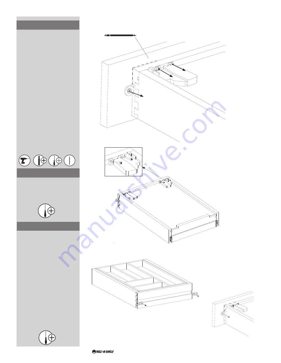
Install the right and left Blum 

release triggers on the bottom of 

the drawer using (4) #6 x 1/2” pan 

head screws 

(See Figure B)

.

FIG. B

FIG. C-1

FIG. C-2

FIG. A

Install the figure 8 brackets onto 

the front of the drawer using the 

screws that come inside of the 

same bag as the figure 8 brackets 

(See Figure C-1)

.

Once the (2) Figure 8 brackets have 

been secured to the drawer box 

align the drawer box to the back of 

the drawer front.

Align the bottom corners of the 

drawer box with the pencil marks 

from Step 1. Drill a 7/64” wide X 

3/8” deep pilot hole through the 

middle of each bracket and into the 

back of the drawer front. 

Be careful 

to not drill through the drawer 

front

. Secure the drawer box to the 

drawer front with (2) Phillips head 

screws 

(See Fig. C-2)

Remove existing drawer box from 

cabinet by squeezing the drawer 

locking devices and pulling the 

drawer box forward.

Use a pencil to trace around the 

bottom two corners of the drawer 

and onto the back of the drawer 

front 

(See Figure A)

.

Remove the screws that secure 

the drawer front to the drawer 

box 

(See Figure A)

. Discard the 

existing drawer box.

Note: Not all existing drawer 

boxes will have release triggers 

like the ones shown in Figure A. 

A EURO roller slide or various 

other drawer slides may involve 

alternate removal methods. 

If your existing drawer box 

is without triggers underneath 

the box, there may be locking 

devices located on the  

slides elsewhere.

STEP 1

Bottom view

#2

#2

Summary of Contents for 4WTCD-343FLSC

Page 1: ...er mount slides or Grass Elite 7523 19 550 533 undermount slides 4WTCD 30 4WTCD 36 with BLUMOTION slides require an additional stabilizer bar which is included in the kit purchase I 4WTCD 0218 THE MAP...

Page 2: ...o the back of the drawer front Be careful to not drill through the drawer front Secure the drawer box to the drawer front with 2 Phillips head screws See Fig C 2 Remove existing drawer box from cabine...

Page 3: ...r kit STEP 4 STEP 5 13 16 21 mm 3 32 2 mm 1 1 4 32 mm 5 8 16 mm 1 1 32 26 mm 15 32 11 6 mm 9 16 14 mm FIG D 13 32 10 mm 1 15 32 37 mm A B 11 32 9 mm 1 8 3 mm Setback Inside cabinet depth Left Side Scr...

Page 4: ...e hardware is engaged The drawer box can be removed by squeezing the arms on the locking devices and pulling forward Once the drawer is installed the corners can be raised lowered by up to 1 8 by slid...

Page 5: ...E 20 MIN I 4WTCD 0218 EL SISTEMA DE CAJONES DE ARCE 4WTCD Y 4VDO EST DISE ADO PARA USARSE SOLO DEBAJO DE LOS ACCESORIOS DE CAJ N DE EXTENSI N COMPLETA SI EST S REEMPLAZANDO UNA CAJA DE CAJ N QUE ACTUA...

Page 6: ...en la Figura A Una corredera de rodillo EURO u otras correderas de caj n pueden implicar m todos alternativos de extracci n Si tu caja de caj n existente no tiene liberadores debajo de la caja puede h...

Page 7: ...e fois que les 2 supports de la figure 8 ont t fix s au bloc tiroir alignez les avec la fa ade arri re du tiroir Alignez les coins inf rieurs du bloc tiroir avec les marques de crayon effectu es lors...

Page 8: ...si n c ssaire pour vous assurer du bon alignement de la fa ade du tiroir avec l armoire STEP 7 FIG F 12400 Earl Jones Way Louisville KY 40299 rev a shelf com Customer Service 800 626 1126 Customer Ser...

Reviews: