FIRST Global Building Guide Created by REV Robotics 2019, Licensed Under CC BY-SA
29
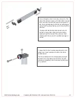
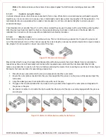
In many cases the number of teeth on the gear or sprocket is not divisible by six, the number of sides on the hex shaft,
and therefore the relative rotation between two of the same part will result in the teeth being out of alignment with each
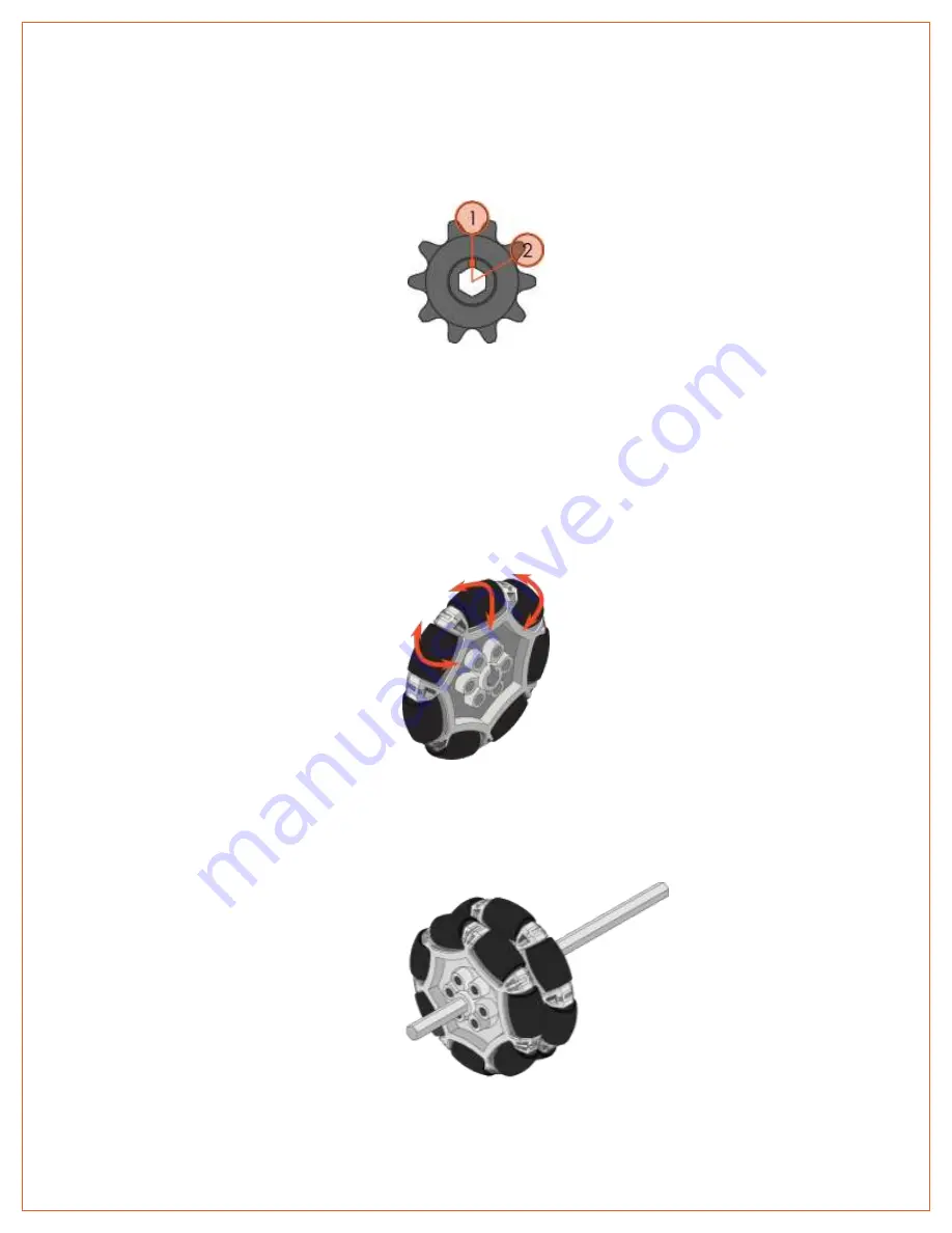
other. As Figure 50 shows, if the first sprocket was put on a shaft with the alignment notch facing upwards (noted by
),
there would be a valley at the top of the sprocket. If the second sprocket was added to the shaft, but rotated clockwise by
60 degrees (by the turn of one flat side), there would be most of a sprocket tooth at the top of that sprocket (noted by
).
It’s possible to build a working system without aligning stacked parts, but it’s not recommended.
Figure 50: Shaft Alignment Example
3.11
WHEELS
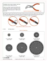
The REV Robotics Building System has three different traction wheel sizes (Table 7) and two different Omni Wheel sizes
(Table 8). Traction wheels and GRIP wheels are co-molded with a polyurethane tread for increased traction.
3.11.1
Omni Wheels
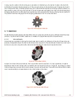
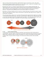
Omni wheels are a special kind of wheel that has smaller rollers round the circumference of the wheel. These rollers can
passively roll perpendicularly to the direction the wheel is driven (Figure 51). This wheel makes it easier for a robot to turn
and can also be used in conjunction with some advanced drivetrains to create more maneuverable robots.
Figure 51: Omni Wheel Rollers
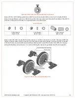
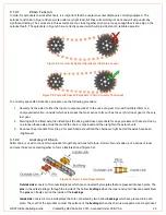
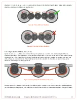
A single omni wheel is the same thickness, 15mm, as all other motion components. In some applications, it might be
desirable to stack two omni wheels, with one rotated by 60° from the other, as shown in Figure 52. By setting your wheels
in this configuration you ensure that a roller is always in contact with the ground. This results in smoother operation and a
more consistent ability to roll perpendicular to the normal rotation of the wheel.
Figure 52: Double Stacked Omni Wheels

