background image

1.8  Seat Adjustments

VI.  SEAT BELTS

Both front and rear seats of your car 
have been fitted with safety belts for 
maximum protection from any 
inadvertent event. 

Instrument Cluster and Controls

The following steps may be followed.
Step 1: Adjust the seats so you can sit 

up straight.

Step 2: Pull the belt across you and 

insert the latch plate into the 
latch slot. Make sure the belt is 
securely latched. Also check that 
the belt is not twisted. 

Step 3: Position the lap belt as low as 

possible across your hips. Then 
pull and adjust the shoulder belt 
so they both fit  snugly. 

To unfasten the belt, press the release 
button on the latch slot.

Make sure all seat-belts are properly 
fastened before driving, for your 
safety.

CAUTION

The Rear seat belts are static type. 
Manually adjust them according to the 
comfort of the occupant to fit snugly.

26

1.8 Seat Adjustments


Instrument Cluster and Controls

III.  HEAD REST

The head rest can be adjusted for height 
with the help of the button located on it. 
To raise, pull the headrest upward to a 
level most comfortable for you. To lower 
it, press the button and push the head 
rest down.

IV.  REAR SEAT ACCESS

You can access the rear seats from both 
sides of your car. To do so:
Step 1:  Pull up the seat adjustment 

lever of the respective front seat 
and slide the seat forward. 

Step 2:  Recline the seat forward to 

allow easy entry to the rear seat.

Step 3:  Make sure the front seat is 

returned back to the normal 
position.

It is dangerous to drive without head 
rest.

CAUTION

V. 

FOLDING REAR SEAT

Step 1 : To get additional luggage 

space, detach the two rubber 
latches located behind the rear 
seat.

Step 2 : Fold the backrest forward.
Step 3 : When not required lift backrest 

and push back to normal 
position attaching the rubber 
latches.

25

Downloaded from 

www.Manualslib.com


manuals search engine


Summary of Contents for G-Wiz

Page 1: ...and assistance contact Email service goingreen co uk web www goingreen co uk Ph 0208 843 0846 8 a m to 6 p m Monday Friday GoinGreen Green Station 201 Beaconsfield Road Southall Middlesex UB1 1DA Down...

Page 2: ...t will be of helpful should you require any assistance We also encourage you to carefully read the Warranty terms and conditions It will help you understand the warranty coverage and responsibilities...

Page 3: ...structions NOTE Obey all safety messages that follow these symbols This asterisk in the manual signifies that an item is an optional extra All information illustrations and specifications in this Owne...

Page 4: ...Do s and Don ts 7 0 Troubleshooting 8 0 Maintenance 9 0 Service Schedule 10 0 G Wiz s Safety Features 11 0 Key Technologies 12 0 Power Pack 13 0 Technical Specifications 14 0 Vehicle identification nu...

Page 5: ...SEAT RECLINING LEVER HATCH OPENING LEVER SEAT SLIDING LEVER HAZARD WARNING SWITCH CONTROL KNOB HEAD LIGHTS TURN SIGNAL LEVER START UP KEY SWITCH PARKING BRAKE FUSE BOX HOOD OPENING LEVER ACCELERATOR P...

Page 6: ...E GREEN REGEN RED EXTRA POWER USAGE Dual colored LED TURN SIGNALS LOW BEAM LIGHT POWER GAUGE PARKING BRAKE LOW BRAKE FLUID LIGHT BATTERY LOW WATER LIGHT HIGH BEAM LIGHT TEMPERATURE LIGHT SPEEDOMETER O...

Page 7: ...rol System 1 6 Keys Key switches 1 7 Door Locks 1 8 Seat Adjustment 1 9 Hood 1 10 Rear Hatch 1 11 Parking Brake 1 12 Roof Lights 1 13 Compartments 1 14 Mirrors Audio system sunvisor 12V socket 7 12 13...

Page 8: ...permanently The light disappears when the charge cable is removed from the charge port II LOW BATTERY LIGHT Red When the State Of Charge SOC in the Power Pack drops to about 35 this light starts flas...

Page 9: ...ates increased charging time due to high Power Pack Charger temperature NOTE Do not charge your car in high ambient temperature conditions or in direct sunlight This will reduce the life of your Power...

Page 10: ...during drive indicates a severe over temperature condition and may completely restrain the car If you continue driving the car electronics may reduce the speed and power in order to limit the heating...

Page 11: ...R knob is at N position This light will blink if the key is switched on with control knob in either B F and R position If this light is blinking the car will not move Please turn the control knob to N...

Page 12: ...ortunity Instrument Cluster and Controls X HIGH BEAM This lamp glows when the high beam headlights are turned on XIII TURN INDICATOR The turn indicator light on the cluster will flash when either of t...

Page 13: ...on short trips between stops Keep track of your odometer reading and check the maintenance schedule regularly for required services Increased wear or damage to certain parts can result from failure t...

Page 14: ...ols III TURN SIGNALS The turn signal lights blink when you signal a lane change or turn Turn the side indicator lever upwards for left turn and downwards for right turn respectively I HEADLIGHTS This...

Page 15: ...come ON for a few seconds wipes Instrument Cluster and Controls V HAZARD WARNING Pull up the switch to activate the hazard warning lights All six external turn signal lights and turn signal indicators...

Page 16: ...tion will give you addition speed acceleration and hill climbing Neutral N The BFNR knob should be in this position at the time of Key on and should be used while parking your car or when you place yo...

Page 17: ...nstrument Cluster and Controls 1 1 2 2 3 3 4 4 BLOWER DEFROSTER SELECTOR LEVER BLOWER HEATER KNOB 12V D C SOCKET DEFOGGER SWITCH REAR FOG LAMP SWITCH A CVARIABLE THERMOSTAT KNOB 16 Downloaded from www...

Page 18: ...t the two corners of the dashboard direct air onto the windows II BLOWER OPERATION The Blower can be operated by turning the knob from OFF position to any of the desired 4 operating positions The louv...

Page 19: ...o operate the Heater pull the blower knob gently towards yourself and turn it to desired position The HEAT symbol in the center of the knob will light up Heater will automatically switch off at 25 SOC...

Page 20: ...ess again to switch it OFF VII REAR DEFOGGER The rear hatch defogger will clear the fog frost or thin ice to give you a clear rear view The defogger can be activated by pressing the defogger switch pr...

Page 21: ...is not applied 1 6 Keys Key Switch Chime I KEYS Your car comes with two identical keys They fit all the locks on your car Key Switch and Doors Each key has an identification number stamped on it It is...

Page 22: ...the occupants from being thrown out in case of accidental opening of a door CAUTION II TO OPEN THE DOOR UNLOCK anti clockwise LOCK clockwise UNLOCK LOCK Your car has been equipped with factory fitted...

Page 23: ...d the car is in the disarmed condition 2 Doors get locked automatically after 30 sec once it is unlocked by the remote 3 Doors get unlocked automatically when you turn OFF the Key Switch BUTTON 1 LOCK...

Page 24: ...h is in the OFF position and the doors are closed 1 Close doors properly while coming out of the car 2 Do not turn the Key Switch ON when the doors are open this makes remote button disabled even afte...

Page 25: ...or backward Instrument Cluster and Controls II RECLINING THE SEAT The seat back can be reclined to four different angles by pulling a lever located on the right hand side of the driver s seat and the...

Page 26: ...seat adjustment lever of the respective front seat and slide the seat forward Step 2 Recline the seat forward to allow easy entry to the rear seat Step 3 Make sure the front seat is returned back to...

Page 27: ...he latch slot Make sure the belt is securely latched Also check that the belt is not twisted Step 3 Position the lap belt as low as possible across your hips Then pull and adjust the shoulder belt so...

Page 28: ...lap Child restraint system Children and infants must never be transported without a proper restraint system This system can be purchased from the market Ensure that the system purchased meets all the...

Page 29: ...d pull the hood support rod out of its clip and insert the end into its housing on the passenger s side Instrument Cluster and Controls II CLOSING THE HOOD Step 1 Lift it up slightly to remove the sup...

Page 30: ...driver s side Lift the hatch II CLOSING THE HATCH Gently press hatch down until it locks into position Do not bang the hatch Secure the hatch fully before driving CAUTION Be very careful of the hatch...

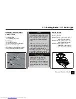
Page 31: ...f Light Instrument Cluster and Controls NOTE In the event the start up key is ON the door is closed and the parking brake is pulled a chime should be heard when you press accelerator pedal This will e...

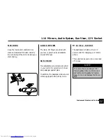
Page 32: ...der The beverage holder can be accessed by pulling it out Be careful when using it A spilled liquid that is very hot can scald you or your passenger Spilled liquids can also damage the upholstery carp...

Page 33: ...justable sun visors are provided in your G Wiz for protection of driver and passenger against glare In addition the passenger side sun visor comes equipped with a vanity mirror IV 12 V D C SOCKET The...

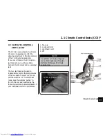
Page 34: ...2 1 Climate Control Seats 34 Climate Control Seats 2 33 Downloaded from www Manualslib com manuals search engine...

Page 35: ...ontrol the temperatures of the two seats To select cool mode pull the switches UP To select heat mode keep the switches pushed in In both the cool and heat modes the following levels can be selected b...

Page 36: ...3 4 Under Charging Over Charging your G Wiz 3 5 Equalizing Charge 3 6 Equalizing by Customer 3 7 Trickle Charging 3 8 Battery Heating 3 9 Charging Precautions 36 38 38 39 40 40 41 41 41 Charging Your...

Page 37: ...follow the 4 steps given below Step 1 Make sure parking brake is engaged Charging your G Wiz Ensure control knob is in neutral N mode Turn start up key to OFF position and remove it from the key slot...

Page 38: ...ble female end Step 4 Plug the other male end into a 15 Amp 220 240V external power source and then switch on power supply to it Your Car is now on charge Check the Power Gauge on the Instrument Clust...

Page 39: ...omputerised system in your car will wait till the temperature of the Power Pack lowers before enabling the charging process 2 In conditions 10 C or 45 C temperature the battery charging duration will...

Page 40: ...rolled on board charger remembers the point at which charging was interrupted and resumes charging from where the charging stopped It also has an auto shut off mechanism by which the charging automati...

Page 41: ...10 hrs for equalization is completed There will be no indication when remaining equalization will happen Charging your Gwiz c There will be no indication if the equalization has not been completed Onc...

Page 42: ...2 Do not plug in with wet hands 3 It is recommended that your car is not in the sun during the charging process 4 Make sure that children are kept away from both on board external charge ports especia...

Page 43: ...42 Downloaded from www Manualslib com manuals search engine...

Page 44: ...4 1 Quick Start 4 2 Estimating Your Driving Range 4 3 Extending Your Driving Range 4 5 Battery Care 44 46 47 48 Driving Your G Wiz 4 43 Downloaded from www Manualslib com manuals search engine...
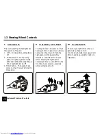
Page 45: ...e take off stage This will enhance your safety and that of pedestrians nearby This mode also enables you to maximise your driving range Step 4 Disengage the parking brake by gently pulling up and turn...

Page 46: ...hen you require a higher degree of acceleration rotate the Control Knob to Boost B mode In this mode you attain a much higher top speed This is electronically limited to 50 mph It is possible for you...

Page 47: ...is due to pre programmed software in your car s Energy Management System EMS and Motor Controller These warning signals ensure as far as possible that you are never stranded on the road due to insuffi...

Page 48: ...average speed acceleration driving range and comfort please ensure that prescribed maximum payload of 227Kgs is not exceeded 5 Avoid hard braking The first 25mm of brake pedal travel will gives you fu...

Page 49: ...ey periodically need equalisation Please make sure that the equalisation goes through regularly Refer Sec 3 5 3 6 Driving your G Wiz 3 Keep Charging If the car is not in use for long periods several d...

Page 50: ...res 5 2 Tyre Pressure 5 3 Tyre Markings 5 4 Tyre Rotation 5 5 Tyre and Wheel Inspection 5 6 Wheel Alignment and Balance 50 50 50 51 51 52 Tyres 5 49 Downloaded from www Manualslib com manuals search e...

Page 51: ...Any underinflated tyre generates excessive heat that may result in reduced life of your tyres Check inflation pressures on all the tyres at least once a month before driving This should be done when...

Page 52: ...in uniform tyre wear It is however essential to get wheel alignment checked After the tyres have been rotated adjust the front and rear inflation pressures as indicated on the door pillar The tyres w...

Page 53: ...ar Replacement of a tyre is needed when 1 The wear indicators are seen at three or more places around the tyre 2 Cord Fabric can be seen showing through the tyres rubber 3 The tread or sidewall is cra...

Page 54: ...6 1 Charging 6 2 Driving 6 3 Servicing 6 4 Installation of Accessories 6 5 Parking 6 6 Maintenance 54 55 56 57 57 57 Do s Don ts 6 53 Downloaded from www Manualslib com manuals search engine...

Page 55: ...keep it on charge The computer controlled on board charger will compensate any normal discharge of power Allow the Power Pack to charge completely whenever possible Top up battery water in the Power...

Page 56: ...ving during the night switch off the head lights when at a traffic signal This will help in conservation of charge in the Power Pack and enhance your driving range Always maintain the recommended tyre...

Page 57: ...turned on Temperature Light flashes after the start up key is turned on Parking Light stays on after the parking brake is disengaged and there is adequate brake fluid Top up the Power Pack water with...

Page 58: ...ion of accessories can damage your car and the manufacturer warranty will become null and Always engage the parking brake while parking your car DO S DON TS 6 4 Parking Do s Don ts Use a damp cloth or...

Page 59: ...58 Downloaded from www Manualslib com manuals search engine...
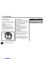
Page 60: ...7 1 Charging 7 2 Driving 60 60 Troubleshooting 7 59 Downloaded from www Manualslib com manuals search engine...

Page 61: ...e external Power Source and or the on board Charge Port and check that power supply is available Charge in shade cooler temperature or during the night when the ambient temperature is reduced POSSIBLE...

Page 62: ...movement of your car If You may have engaged the RNFB knob to other positions other than Neutral N and pressed the accelerator The Motor Controller or Power Pack may have got heated up The Power Pack...

Page 63: ...ven tyre pressure Low or uneven tyre pressure disturbed Wheel Alignment Low or uneven tyre pressure disturbed Wheel Alignment Low or uneven tyre pressure Excessive tyre pressure Incorrect wheel balanc...

Page 64: ...shield properly Press button1 of remote twice to deactivate this condition POSSIBLE CAUSE REMEDY Appearance of Service light can be due to temporary condition read by the EMS On board computer Please...

Page 65: ...64 Downloaded from www Manualslib com manuals search engine...
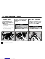
Page 66: ...ghts 8 4 Fuse Box 8 5 Power Pack 8 6 Windscreen Washer and Wiper 8 7 Storing your Car 8 8 Appearance Care 8 9 Towing your Car 66 66 67 69 70 72 73 73 75 Maintenance 8 65 Downloaded from www Manualslib...

Page 67: ...ate tread and correctly inflated Inflation Keeping the tyres properly inflated provides the best combination of handling tread life and riding comfort Underinflated tyres wear unevenly adversely affec...

Page 68: ...OF BULBS Headlight 1 Open the Bonnet and engage the support rod 2 Disconnect the wiring harness connector from the rear of bulb 3 Pull the rubber cap out 4 Release the bulb retaining spring and remove...

Page 69: ...the 2 screws in case of turn indicator and reverse lamp 2 Rotate the bulb anticlockwise and remove it 3 Pull out the bulb from the bulb holder 4 Replace the bulb with a new one 5 Install in the revers...

Page 70: ...5 A Turn Signals Reverse 7 Lights F 7 5 A Wiper and Washer 8 F 5A Fog lamps 9 F 15 A CDL Lighting 10 F A CDL Controls 11 F 7 5 A Blower Relay Rear 12 Defogger F 5A Condensor fan 16 3 8 4 Fuse Box Main...

Page 71: ...e of the fuse box cover Replace the fuse box cover to its original position Maintenance POWER PACK The power pack requires to be topped with distilled water every 500 miles or whenever the battery wat...

Page 72: ...minutes depending on the water level in your power pack When full the flow indicator will stop revolving indicating that the power pack has stopped the intake of water Hold the water flow indicator on...

Page 73: ...the wiper blade with foreign matter can reduce the effectiveness of the windscreen wiper If the blades are not wiping properly it could be time to replace the wiper blade To replace the wiper blade p...

Page 74: ...it looking new Here are some tips on preserving the appearance of your car A Exterior i Washing Dirt and grit can scratch the paint while tree sap and bird droppings can permanently ruin the finish R...

Page 75: ...s Use a soft cloth or paper towels to clean all glass and clear plastic surfaces Do not use spray water in the interior of your car Doing so car can result in damage s to the various electronics compo...

Page 76: ...t both front ends LH RH of the chassis frame immediately behind the front bumper for fixing the tow hook Fix the hook by turning it in either of the holes as per your convenience Tie one end of the to...

Page 77: ...76 Downloaded from www Manualslib com manuals search engine...

Page 78: ...ering Sub assembly 9 3 Brake Sub assembly 9 4 Transmission Sub assembly 9 5 Wheels and Tyres 9 6 Body 9 7 Electrical Electronics Sub assembly 78 78 78 79 79 79 80 Maintenance Schedule 9 77 Downloaded...

Page 79: ...r Brake Pipes Hoses leakage damage Brake Pedal Bush Parking Brake Lever Cable play damage Regen Braking Service at the interval listed x 1 000 miles or number of months whichever comes first I I I I I...

Page 80: ...ling looseness I I I R I I I I I I I T 9 4 TRANSMISSION SUB ASSEMBLY I I I I I I I I I T I L T I I I R I I I I I I T I L T I I I I I I I I R I T I L T I I I R I I I I I I T I L T I I I I I I I I I T I...

Page 81: ...every 500 miles or when LOW BATTERY LIGHT comes ON I A I I I I I I I I C C L C I I I I I A I I I I I I I I C C L C I I I I I A I I I I I I I I C C L C I I I I I A I I I I I I I I C C L C I I I I I A I...

Page 82: ...10 0 Your Car s Safety features 82 Your G Wiz Safety Features 10 81 Downloaded from www Manualslib com manuals search engine...

Page 83: ...s cocoons passengers in an inadvertent accident Dent Proof Body Panels Most accidents in cities involve low speed skirmishes with other vehicles often leaving owners with expensive tinkering jobs The...

Page 84: ...11 1 Steel Space Frame Chassis 11 2 Motor Controller 11 3 Energy Management System 84 84 85 Key Technologies 11 83 Downloaded from www Manualslib com manuals search engine...
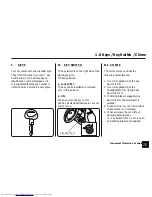
Page 85: ...range Repairs Quick and economical Key Technologies MOTOR CONTROLLER Salient Features It converts power pack voltage to required AC voltage and current to the motor It performs regenerative braking t...

Page 86: ...ious lamps to function These include 1 Charge Light 2 Power Pack Low Battery Water Light 3 Low battery light 4 Parking Brake ON in drive mode 5 Low Brake Fluid level 6 Neutral light 7 Temperature ligh...

Page 87: ...86 Downloaded from www Manualslib com manuals search engine...

Page 88: ...12 2 Life Span 12 3 Integrated Systems 12 4 Servicing 12 5 Extending the Life of the Power Pack 12 6 Power pack Heater pad 88 88 88 88 89 90 Power Pack 12 87 Downloaded from www Manualslib com manuals...

Page 89: ...driving range the Power Pack should last approximately 3 years Power Pack 12 3 INTEGRATED SYSTEMS IN THE POWER PACK Centralised Water Top up System Water Level Sensor Battery Temperature Sensor Indivi...

Page 90: ...needle indicator in the power gauge is on the red band In the event you are not using your car for more than one week it needs proper storing and plugged in for charging so trickle charge can take pl...

Page 91: ...continuously plugged into the mains power even after full charging so as to keep the battery heating system active as the battery heating system is powered by the mains voltage and operates through t...

Page 92: ...r Pack 13 5 Motor Controller 13 6 Suspension Type 13 7 Tyres 13 8 Controls 13 9 Electricals 13 10 Braking System 13 11 Body Panels Bumpers 92 92 92 93 93 93 93 93 93 94 94 Specifications 13 91 Downloa...

Page 93: ...Tubular Steel Space Frame A 20 drop will be noticed in the driving range if A C or Heater or Wiper is in use during drive NOTE Estimated range Estimated top speed Maximum gradeability Estimated charge...

Page 94: ...Brake and Accelerator 4 operating modes B F N R 13 8 CONTROLS The RNFB switch provides Reverse Neutral Foward Boost power modes of operation Headlights Park front Front Rear Indicators Side Indicators...

Page 95: ...brake Front 19 05 mm Rear 15 87 mm Parking brake mechanically actuated on the rear wheels Regenerative Braking to enhance the driving range Low Brake Fluid Warning provided on the Instrument Cluster...

Page 96: ...Vehicle identification numbers 14 95 Downloaded from www Manualslib com manuals search engine...

Page 97: ...t cross member near windshield wiper washer unit under the hood LOCATION OF MOTOR NUMBER Motor number is punched on the body ofthemotor LOCATION OF CHASSIS NUMBER Chassis number is punched on the chas...

Page 98: ...Index 15 97 Downloaded from www Manualslib com manuals search engine...

Page 99: ...ing Installation of Accessories Maintenance Parking Servicing Door Locks Door Pocket Driving Range Estimating Extending Driving Reva E Energy Management System EMS Equalisation Charge F Forward F mode...

Page 100: ...ts Seat Front Adjustment Reclining Seat Rear Access Folding Seatbelts Service Light Specifications Speedometer State of charge SOC Steel Space Frame Chassis Storing your car 44 34 15 30 85 24 24 24 25...

Reviews: