background image

PUSH FOR F

AN

M I N U T

E S

LO HI INT

g)

g) Intermittent Switch

(IC 100-5V)

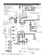
Wiring Diagram (Superior, Project, Economy and Maxum Series Unit) 

5

CONTROL BOARD:

a) Timer Switch (TC100)
b) Wall Switch
c) Dehumidistat 
d) Time Delay Switch (TC100-120 & TC100-120P)
e) Master On/Off Switch 
    for HRV/ERV
f ) Light

Optional Accessories (Not Supplied)

F

AN2

F

AN1

LINE

NEUTRAL

PUSH FOR F

AN

M I N U T

E S

or

a)

b)

c)

d)

Hi

Low

Light / Switch Option

120 Vac / 1 / 60Hz

Power Supply

Hi

Low

Furnace, Fan Coil, 

Heat Pump

Interlock

4 - Speed Controller for Manual Balancing

and 

Air Flow 

Adjustment

120 VAC / 1 / 60Hz

Power Supply

Ground

Fuse

On

Off

e)

Low

High

Low

High

Exhaust

Fan Speed

Supply

Fan Speed

Supply Fan  Exhaust Fan 

b)

Temp. Sensor

Safety Switch

Low Voltage

+5

DA

T

C

Speed

Contact

L0/HI

SPEED

HV INPUT

Remote

0n/0ff

(HV-High Voltage)

NC

C

N0

Ext. Interlock

HIGH VOLTAGE

Damper Interlock

NC

C0M

N0

f)

HRV/ ERV
Hi / Low

Light
On / Off

120 Vac / 1 / 60Hz

Power Supply

Jumper

(remove jumper to install 

 master ON/OFF switch)

b)

L0/HI

Speed 

HV Input

Remote

0n/0ff

HV

NC

C

N0

Ext. Interlock

HIGH VOLTAGE

FAN #

1 - Single speed 


(Bathroom Exhaust fan connection for “Project Series”)

Note: 

Up to 4 Timer Switches (TC 100-5V)

can be connected to control board of 

HRV/ERV by using three 24 AWG (min.) 
Copper wires as shown.
Maximum total wire length 75ft. 
(see option 2)

Option 2:

Timer

Switch 

2

Timer

Switch 

3

Timer

Switch 

4


to Control 

Board

Note: 

Make sure, the 

Line

 must be connected to 

Line

 and 

Neutral

 connected to 

Neutral

Unit will not function if not connected correctly. 

RED

YEL

GND

RED

YEL

GND

C

+5

DAT

RED

YEL

GND

RED

YEL

GND

Model # RHRV-P100A
              RHRV-P100P
              RERV-P100

Note:

 Same power source must be 

used if wall switches (b) & time delay switches (d) 
are connected together in parallel. 

TC100-120P

TC100-120

RED

BLACK

WHITE

Ground

120 Vac / 1 / 60Hz

Power Supply

(TC100-5V)

Important Note:-

 When installing timers or time delay switches, make sure 

                             that they are for appropriate HRV/ERV models.

Ground

BLACK

WHITE

RED

Damper Motor

(Single Winding)

External Damper

Motor

Ground

Intermittent

OR  Timer  

RED

YEL

GND

Option-1

(Also available w/o OFF
mode)

Switch 1

and one intermittent switch (IC 100-5V)

Summary of Contents for Economy Series

Page 1: ...c com Maxum Series model RHRV S200A Aluminum Core RHRV S200P Polypropylene Core RERV S200 Enthalpy Core Economy Series model RHRV E100A Aluminum Core RHRV E100P Polypropylene Core RERV E100 Enthalpy Core Superior Series model RHRV S100A Aluminum Core RHRV S100P Polypropylene Core RERV S100 Enthalpy Core C US 2100 CERTIFIED Project Series model RHRV P100A Aluminum Core RHRV P100P Polypropylene Core...

Page 2: ...ng or cleaning these unit it is suggested to wear safety glasses and gloves 9 Do not use this unit for commercial purpose 10 For residential use only The unit must be grounded 11 Do not install in a cooking area 12 This unit is not designed to exhaust combustion and or dilution air for fuel burning appliances CAUTION 1 Turn the unit OFF during construction or repair to avoid filter blockage 2 Exhau...

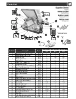
Page 3: ...ypropylene Backdraft Damper 014043 2 2 2 6 Blower Exhaust Supply 9317 2 2 2 7 Adjustable Door Latch 9319 1 1 1 8 Drain Spout Assembly 9320 1 1 1 9 Core Locking Bracket 9321 1 1 1 10 Nut 014016 1 1 1 11 Safety Switch 9322 1 1 1 12 Main Control Board Superior Project 9356 1 1 1 Main Control Board Bracket 9355 2 2 2 13 Door Hinges 9328 1 Set 1 Set 1Set 14 Extension Box Cover 9329 1 1 1 15 Mounting Br...

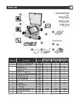
Page 4: ...embly 9315 1 1 1 2 Polypropylene Collar 5 Dia 014043C 2 2 2 3 Aluminum Core 9312 1 n a n a Polypropylene Core 9313 n a 1 n a Enthalpy Core 9314 n a n a 1 Filter 7 x 12 MERV 4 9358 2 2 2 4 Temperature Sensor 9326 1 1 1 5 5 ø Polypropylene Backdraft Damper 014043 2 2 2 6 Blower Supply 9317 1 1 1 7 Adjustable Door Latch 9319 1 1 1 8 Drain Spout Assembly 9320 2 2 2 9 Core Locking Bracket 9321 1 1 1 10...

Page 5: ...per 014043 2 2 2 5 Adjustable Door Latch 9319 1 1 1 6 Drain Spout Assembly 9320 2 2 2 7 Core Locking Bracket 9321 1 1 1 8 Nut 014016 1 1 1 9 Door Hinges 9328 1 Set 1 Set 1 Set 10 Mounting Brackets 011135 4 4 4 11 T Connector 9330 1 1 1 12 Webbing Brackets Ladder Locks 9332 2 Sets 2 Sets 2 Sets 13 Chains Springs Brackets 9354 1 Set 1 Set 1 Set 14 Drain Pipe 9331 1 1 1 Economy Series model RHRV E100...

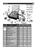
Page 6: ...ore 9394 n a n a 1 Filter 10 1 2 x 12 MERV 4 9395 2 2 2 4 Temperature Sensor 9326 1 1 1 5 6 ø Polypropylene Backdraft Damper PBD6 2 2 2 6 Blower Supply Exhaust 013070 2 2 2 7 Adjustable Door Latch 9319 1 1 1 8 Drain Spout Assembly 9320 2 2 2 9 Core Locking Bracket 9321 1 1 1 10 Nut 014016 1 1 1 11 Safety Switch 9322 1 1 1 12 Main Control Board Superior Project 9356 1 1 1 Main Control Board Bracket...

Page 7: ... ON OFF switch b L0 HI Speed HV Input Remote 0n 0ff HV NC C N0 Ext Interlock HIGH VOLTAGE FAN 1 Single speed Bathroom Exhaust fan connection for Project Series Note Up to 4 Timer Switches TC 100 5V can be connected to control board of HRV ERV by using three 24 AWG min Copper wires as shown Maximum total wire length 75ft see option 2 Option 2 Timer Switch 2 Timer Switch 3 Timer Switch 4 to Control ...

Page 8: ...hermostat and thereby turning on the cooling system If you identify this type of thermostat you must use the Alternate Interlock Wiring For a furnace connected to a cooling system Wiring Diagram cont d 6 Furnace Fan Coil Heat Pump Interlock Standard Interlock Wiring W R G Y W R G Y C FOUR WIRE TWO WIRE heating only Cooling System THERMOSTAT TERMINALS TWO WIRE Never connect a 120 volt AC circuit to...

Page 9: ...um Fully Ducted System With Fan Coil System FRESH AIR EXHAUSTED AIR Balancing Box Fan coil Unit HRV ERV Fan coil Unit HRV ERV NOTE This is a stand alone HRV ERV system which is not connected to a force air system Stale air is drawn from key areas of the home bathroom kitchen while fresh air is supplied to main living areas Fully Ducted System for Superior Maxum series only Note All Exhaust vents m...

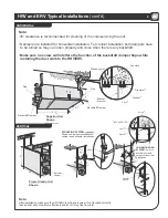
Page 10: ...onal Allows one person installation for vertical and horizontal installation VERTICAL Note After installation make sure the HRV ERV is properly leveled If not levelled correctly then defrost will not perform effectively and or unit may frost in winter Note UP UP PULL DOWN Strap jtant ay 01 2 8 11 NOT SUPPLIED jtantay 12 23 11 Vibration Spring Washer Screw CHAIN MOUNTING SYSTEM optional Available f...

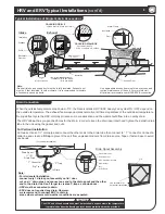
Page 11: ... HRV and ERV Typical Installations cont d Typical Installations of Single Vents Access door For vertical installation Use this drain for horizontal installation Fresh air intake and supply duct must be totally insulated Exhaust duct must be 5 feet insulated In colder climate it is recommended to insulate all exhaust and supply ducts Note Use appropriate access door size for easy access and routine...

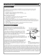
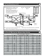
Page 12: ...her duct The flows should now be balanced Actual airflow can be determined from the gauge metre reading The value read on the gauge is called the velocity pressure and on the flow meter is called air velocity FPM The Pitot tube comes with a chart that will give the air flow velocity based on the velocity pressure indicated by the gauge This velocity will be in either feet per minute or metres per seco...

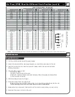
Page 13: ...nly for superior series For balancing extension box cover plate is provided with 3 holes on supply side and 3 holes on exhaust side Do not use pitot tube to open holes in the insulation as it may block damage the pitot tube Take 3 readings on each hole and average all 9 readings for supply and same for exhaust After finish balancing plug all six holes with plastic plugs provided with the unit Exten...

Page 14: ...the filters twice a year Remove the filters Vacuum to remove most of the dust Wash with a mixture of warm water and mild soap Rinse thoroughly and shake filters to remove water and let dry 5 Oil defrost damper levers and hinges 6 Check the exterior fresh air supply hood Make sure there are no leaves twigs grass ice or snow that could be drawn into the vent Partial blocking of this air vent could caus...

Page 15: ... the HRV ERV core Do not use pressure washer on the HRV ERV core Do not place the HRV ERV core in dishwasher Do not use bleach or chlorine Annual Maintenance 5 Cleaning the Fans Fans may accumulate dirt causing an imbalance and or excessive vibration on the HRV ERV A reduction in the air flow may also occur In new construction this may result within the first year due to heavy dust and may occur per...

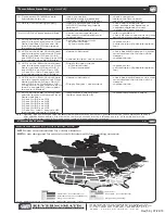
Page 16: ... the remote wall mount Timer Switch will flash 0 5 second On then 2 seconds Off then repeat the cycle 1 Blink Exhaust fan open circuit a motor burned b fan overheated replace motor call technician if possible replace fan 5 Unit is not defrosting properly fresh air duct maybe frozen HRV ERV airflow improperly balanced Temp sensor maybe defective check and remove the ice have professional balancer or ...

Reviews: